 Processor
Dell™ OptiPlex™ GX620
User's Guide

|
CAUTION: Before you begin any of the procedures in this section, follow the safety instructions in the Product Information Guide. |
|
|
CAUTION: To guard against electrical shock, always unplug your computer from the electrical outlet before removing the cover. |

|
NOTICE: When replacing the processor, do not touch the underside of the new processor. |
|
|
NOTICE: When replacing the processor, do not touch any of the pins inside the socket or allow any objects to fall on the pins in the socket. |
|
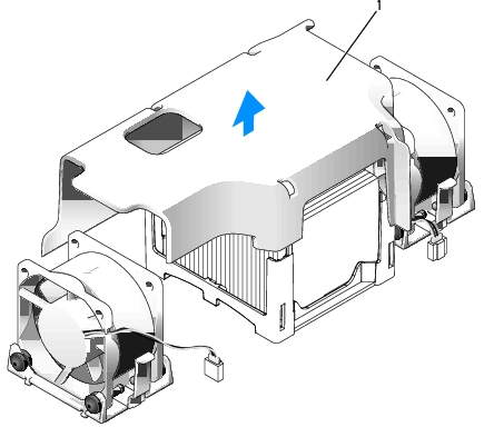
1 |
fan shroud |
|
|
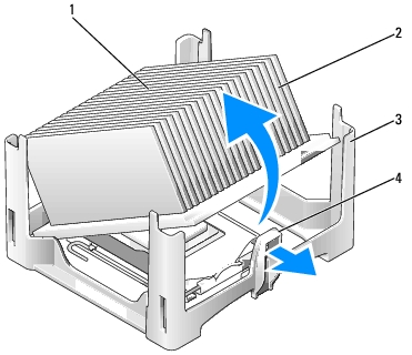
CAUTION: The heat sink can get extremely hot. Be sure the heat sink has had sufficient time to cool before you touch it. |
|
1 |
top of heat sink |
|
2 |
heat sink |
|
3 |
retention base |
|
4 |
release lever |
|
|
NOTICE: Lay the heat sink down on its top, with the thermal grease facing upward. |
|
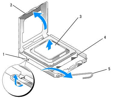
1 |
center cover latch |
|
2 |
processor cover |
|
3 |
processor |
|
4 |
socket |
|
5 |
release lever |
|
|
NOTICE: Ground yourself by touching an unpainted metal surface on the back of the computer. |
|
|
NOTICE: When replacing the processor, do not touch any of the pins inside the socket or allow any objects to fall on the pins in the socket. |
|
|
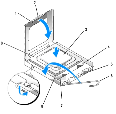
NOTICE: To avoid damage, ensure that the processor aligns properly with the socket, and do not use excessive force when you install the processor. |
|
1 |
processor cover |
6 |
release lever |
|
2 |
tab |
7 |
front alignment-notch |
|
3 |
processor |
8 |
socket and processor pin-1 indicator |
|
4 |
processor socket |
9 |
rear alignment-notch |
|
5 |
center cover latch |
|
|
If you are installing a processor replacement kit from Dell, return the processor to Dell in the same package in which your replacement kit was sent.
|
|
NOTICE: Ground yourself by touching an unpainted metal surface on the back of the computer. |

|
1 |
heat sink |
|
2 |
retention base |
|
3 |
release lever |