canvas elementa elements, button elements, input elements whose type attribute are in the Checkbox or Radio Button states, and input elements that are buttons.widthheightinterface HTMLCanvasElement : HTMLElement {
attribute unsigned long width;
attribute unsigned long height;
DOMString toDataURL(optional DOMString type, any... args);
void toBlob(FileCallback? _callback, optional DOMString type, any... args);
object? getContext(DOMString contextId, any... args);
};
The canvas element provides scripts with a
resolution-dependent bitmap canvas, which can be used for rendering
graphs, game graphics, or other visual images on the fly.
Authors should not use the canvas element in a
document when a more suitable element is available. For example, it
is inappropriate to use a canvas element to render a
page heading: if the desired presentation of the heading is
graphically intense, it should be marked up using appropriate
elements (typically h1) and then styled using CSS and
supporting technologies such as XBL.
When authors use the canvas element, they must also
provide content that, when presented to the user, conveys
essentially the same function or purpose as the bitmap canvas. This
content may be placed as content of the canvas
element. The contents of the canvas element, if any,
are the element's fallback content.
In interactive visual media, if scripting is enabled for the
canvas element, and if support for canvas
elements has been enabled, the canvas element
represents embedded content consisting of
a dynamically created image.
In non-interactive, static, visual media, if the
canvas element has been previously painted on (e.g. if
the page was viewed in an interactive visual medium and is now being
printed, or if some script that ran during the page layout process
painted on the element), then the canvas element
represents embedded content with the
current image and size. Otherwise, the element represents its
fallback content instead.
In non-visual media, and in visual media if scripting is disabled for the
canvas element or if support for canvas
elements has been disabled, the canvas element
represents its fallback content
instead.
When a canvas element represents
embedded content, the user can still focus descendants
of the canvas element (in the fallback
content). When an element is focused, it is the target of
keyboard interaction events (even though the element itself is not
visible). This allows authors to make an interactive canvas
keyboard-accessible: authors should have a one-to-one mapping of
interactive regions to focusable elements in the fallback
content. (Focus has no effect on mouse interaction
events.) [DOMEVENTS]
The canvas element has two attributes to control the
size of the coordinate space: width and height. These
attributes, when specified, must have values that are valid non-negative
integers. The rules for parsing
non-negative integers must be used to obtain their numeric
values. If an attribute is missing, or if parsing its value returns
an error, then the default value must be used instead. The
width attribute defaults to
300, and the height
attribute defaults to 150.
The intrinsic dimensions of the canvas element equal
the size of the coordinate space, with the numbers interpreted in
CSS pixels. However, the element can be sized arbitrarily by a
style sheet. During rendering, the image is scaled to fit this layout
size.
The size of the coordinate space does not necessarily represent the size of the actual bitmap that the user agent will use internally or during rendering. On high-definition displays, for instance, the user agent may internally use a bitmap with two device pixels per unit in the coordinate space, so that the rendering remains at high quality throughout.
When the canvas element is created, and subsequently
whenever the width and height attributes are set (whether
to a new value or to the previous value), the bitmap and any
associated contexts must be cleared back to their initial state and
reinitialized with the newly specified coordinate space
dimensions.
When the canvas is initialized, its bitmap must be cleared to transparent black.
When a canvas element does not represent its
fallback content, it provides a paint
source whose width is the element's intrinsic width, whose
height is the element's intrinsic height, and whose appearance is
the element's bitmap.
The width and
height IDL
attributes must reflect the respective content
attributes of the same name, with the same defaults.
Only one square appears to be drawn in the following example:
  // canvas is a reference to a <canvas> element
  var context = canvas.getContext('2d');
  context.fillRect(0,0,50,50);
  canvas.setAttribute('width', '300'); // clears the canvas
  context.fillRect(0,100,50,50);
  canvas.width = canvas.width; // clears the canvas
  context.fillRect(100,0,50,50); // only this square remains
getContext(contextId [, ... ])Returns an object that exposes an API for drawing on the canvas. The first argument specifies the desired API. Subsequent arguments are handled by that API.
This specification defines the "2d" context below. There is also
a specification that defines a "webgl" context. [WEBGL]
The list of defined contexts is given on the WHATWG Wiki CanvasContexts page. [WHATWGWIKI]
Returns null if the given context ID is not supported or if the
canvas has already been initialized with some other (incompatible)
context type (e.g. trying to get a "2d" context after getting a
"webgl" context).
A canvas element can have a primary
context, which is the first context to have been obtained for
that element. When created, a canvas element must not
have a primary context.
The getContext(contextId, args...)
method of the canvas element, when invoked, must run
the following steps:
Let contextId be the first argument to the method.
If contextId is not the name of a context supported by the user agent, return null and abort these steps.
An example of this would be a user agent that
theoretically supports the "webgl" 3D context, in the case
where the platform does not have hardware support for OpenGL and
the user agent does not have a software OpenGL implementation.
Despite the user agent recognising the "webgl" name, it would return
null at this step because that context is not, in practice,
supported at the time of the call.
If the element has a primary context and that context's entry in the WHATWG Wiki CanvasContexts page does not list contextId as a context with which it is compatible, return null and abort these steps. [WHATWGWIKI]
If the element does not have a primary context, let the element's primary context be contextId.
If the getContext() method has
already been invoked on this element for the same contextId, return the same object as was returned
that time, and abort these steps. The additional arguments are
ignored.
Return a new object for contextId, as defined by the specification given for contextId's entry in the WHATWG Wiki CanvasContexts page. [WHATWGWIKI]
New context types may be registered in the WHATWG Wiki CanvasContexts page. [WHATWGWIKI]
Anyone is free to edit the WHATWG Wiki CanvasContexts page at any time to add a new context type. These new context types must be specified with the following information:
The value of contextID that will return the object for the new API.
A link to a formal specification of the context type's API. It could be another page on the Wiki, or a link to an external page. If the type does not have a formal specification, an informal description can be substituted until such time as a formal specification is available.
The list of context types that are compatible with this one (i.e. that operate on the same underlying bitmap). This list must be transitive and symmetric; if one context type is defined as compatible with another, then all types it is compatible with must be compatible with all types the other is compatible with.
Vendors may also define experimental contexts using the syntax
vendorname-context, for example,
moz-3d. Such contexts should be registered in the
WHATWG Wiki CanvasContexts page.
toDataURL( [ type, ... ])Returns a data: URL for the image in the canvas.
The first argument, if provided, controls the type of the image
to be returned (e.g. PNG or JPEG). The default is image/png; that type is also used if the given
type isn't supported. The other arguments are specific to the
type, and control the way that the image is generated, as given in
the table below.
When trying to use types other than "image/png",
authors can check if the image was really returned in the
requested format by checking to see if the returned string starts
with one of the exact strings "data:image/png," or "data:image/png;". If it does, the image is PNG,
and thus the requested type was not supported. (The one exception
to this is if the canvas has either no height or no width, in
which case the result might simply be "data:,".)
toBlob(callback [, type, ... ])Creates a Blob object representing a file
containing the image in the canvas, and invokes a callback with a
handle to that object.
The second argument, if provided, controls the type of the
image to be returned (e.g. PNG or JPEG). The default is image/png; that type is also used if the given
type isn't supported. The other arguments are specific to the
type, and control the way that the image is generated, as given in
the table below.
The toDataURL() method
must run the following steps:
If the canvas element's origin-clean
flag is set to false, throw a SecurityError exception
and abort these steps.
If the canvas has no pixels (i.e. either its horizontal
dimension or its vertical dimension is zero) then return the string
"data:," and abort these steps. (This is the
shortest data:
URL; it represents the empty string in a text/plain resource.)
Let file be a serialization of the image as a file, using the method's arguments (if any) as the arguments.
The toBlob() method
must run the following steps:
If the canvas element's origin-clean
flag is set to false, throw a SecurityError exception
and abort these steps.
Let callback be the first argument.
Let arguments be the second and subsequent arguments to the method, if any.
If the canvas has no pixels (i.e. either its horizontal dimension or its vertical dimension is zero) then let result be null.
Otherwise, let result be a
Blob object representing a serialization of the
image as a file, using arguments. [FILEAPI]
Return, but continue running these steps asynchronously.
If callback is null, abort these steps.
Queue a task to invoke the
FileCallback callback with result as its argument. The task source
for this task is the canvas blob serialization task
source. [FILESYSTEMAPI]
When a user agent is to create a serialization of the image as a file, optionally with some given arguments, it must create an image file in the format given by the first value of arguments, or, if there are no arguments, in the PNG format. [PNG]
If arguments is not empty, the first value must be interpreted as a MIME type giving the format to use. If the type has any parameters, it must be treated as not supported.
For example, the value "image/png" would
mean to generate a PNG image, the value "image/jpeg"
would mean to generate a JPEG image, and the value
"image/svg+xml" would mean to generate an SVG image
(which would probably require that the implementation actually keep
enough information to reliably render an SVG image from the canvas).
User agents must support PNG ("image/png"). User
agents may support other types. If the user agent does not support
the requested type, it must create the file using the PNG format. [PNG]
User agents must convert the provided type to ASCII lowercase before establishing if they support that type.
For image types that do not support an alpha channel, the serialized image must be the canvas image composited onto a solid black background using the source-over operator.
If the first argument in arguments gives a type corresponding to one of the types given in the first column of the following table, and the user agent supports that type, then the subsequent arguments, if any, must be treated as described in the second cell of that row.
| Type | Other arguments | Reference |
|---|---|---|
image/jpeg
| The second argument, if it is a number in the range 0.0 to 1.0 inclusive, must be treated as the desired quality level. If it is not a number or is outside that range, the user agent must use its default value, as if the argument had been omitted. | [JPEG] |
For the purposes of these rules, an argument is considered to be
a number if it is converted to an IDL double value by the rules for
handling arguments of type any in the Web IDL
specification. [WEBIDL]
Other arguments must be ignored and must not cause the user agent to throw an exception. A future version of this specification will probably define other parameters to be passed to these methods to allow authors to more carefully control compression settings, image metadata, etc.
This specification defines the 2d context type, whose
API is implemented using the CanvasRenderingContext2D
interface.
When the getContext()
method of a canvas element is to return a new object for the contextId 2d, the user agent must return a
new CanvasRenderingContext2D object. Any additional
arguments are ignored.
The 2D context represents a flat Cartesian surface whose origin (0,0) is at the top left corner, with the coordinate space having x values increasing when going right, and y values increasing when going down.
interface CanvasRenderingContext2D {

  // back-reference to the canvas
  readonly attribute HTMLCanvasElement canvas;

  // state
  void save(); // push state on state stack
  void restore(); // pop state stack and restore state

  // compositing
           attribute double globalAlpha; // (default 1.0)
           attribute DOMString globalCompositeOperation; // (default source-over)

  // colors and styles (see also the CanvasLineStyles interface)
           attribute any strokeStyle; // (default black)
           attribute any fillStyle; // (default black)
  CanvasGradient createLinearGradient(double x0, double y0, double x1, double y1);
  CanvasGradient createRadialGradient(double x0, double y0, double r0, double x1, double y1, double r1);
  CanvasPattern createPattern((HTMLImageElement or HTMLCanvasElement or HTMLVideoElement) image, DOMString repetition);

  // shadows
           attribute double shadowOffsetX; // (default 0)
           attribute double shadowOffsetY; // (default 0)
           attribute double shadowBlur; // (default 0)
           attribute DOMString shadowColor; // (default transparent black)

  // rects
  void clearRect(double x, double y, double w, double h);
  void fillRect(double x, double y, double w, double h);
  void strokeRect(double x, double y, double w, double h);

  // path API (see also CanvasPathMethods)
  void beginPath();
  void fill();
  void fill(Path path);
  void stroke();
  void stroke(Path path);
  void drawSystemFocusRing(Element element);
  void drawSystemFocusRing(Path path, Element element);
  boolean drawCustomFocusRing(Element element);
  boolean drawCustomFocusRing(Path path, Element element);
  void scrollPathIntoView();
  void scrollPathIntoView(Path path);
  void clip();
  void clip(Path path);
  boolean isPointInPath(double x, double y);
  boolean isPointInPath(Path path, double x, double y);

  // text (see also the CanvasText interface)
  void fillText(DOMString text, double x, double y, optional double maxWidth);
  void strokeText(DOMString text, double x, double y, optional double maxWidth);
  TextMetrics measureText(DOMString text);

  // drawing images
  void drawImage((HTMLImageElement or HTMLCanvasElement or HTMLVideoElement) image, double dx, double dy);
  void drawImage((HTMLImageElement or HTMLCanvasElement or HTMLVideoElement) image, double dx, double dy, double dw, double dh);
  void drawImage((HTMLImageElement or HTMLCanvasElement or HTMLVideoElement) image, double sx, double sy, double sw, double sh, double dx, double dy, double dw, double dh);

  // pixel manipulation
  ImageData createImageData(double sw, double sh);
  ImageData createImageData(ImageData imagedata);
  ImageData getImageData(double sx, double sy, double sw, double sh);
  void putImageData(ImageData imagedata, double dx, double dy);
  void putImageData(ImageData imagedata, double dx, double dy, double dirtyX, double dirtyY, double dirtyWidth, double dirtyHeight);
};
CanvasRenderingContext2D implements CanvasTransformation;
CanvasRenderingContext2D implements CanvasLineStyles;
CanvasRenderingContext2D implements CanvasPathMethods;
CanvasRenderingContext2D implements CanvasText;

[NoInterfaceObject]
interface CanvasTransformation {
  // transformations (default transform is the identity matrix)
  void scale(double x, double y);
  void rotate(double angle);
  void translate(double x, double y);
  void transform(double a, double b, double c, double d, double e, double f);
  void setTransform(double a, double b, double c, double d, double e, double f);
};

[NoInterfaceObject]
interface CanvasLineStyles {
  // line caps/joins
           attribute double lineWidth; // (default 1)
           attribute DOMString lineCap; // "butt", "round", "square" (default "butt")
           attribute DOMString lineJoin; // "round", "bevel", "miter" (default "miter")
           attribute double miterLimit; // (default 10)
};

[NoInterfaceObject]
interface CanvasText {
  // text
           attribute DOMString font; // (default 10px sans-serif)
           attribute DOMString textAlign; // "start", "end", "left", "right", "center" (default: "start")
           attribute DOMString textBaseline; // "top", "hanging", "middle", "alphabetic", "ideographic", "bottom" (default: "alphabetic")
};

[NoInterfaceObject]
interface CanvasPathMethods {
  // shared path API methods
  void closePath();
  void moveTo(double x, double y);
  void lineTo(double x, double y);
  void quadraticCurveTo(double cpx, double cpy, double x, double y);
  void bezierCurveTo(double cp1x, double cp1y, double cp2x, double cp2y, double x, double y);
  void arcTo(double x1, double y1, double x2, double y2, double radius);
  void arcTo(double x1, double y1, double x2, double y2, double radiusX, double radiusY, double rotation);
  void rect(double x, double y, double w, double h);
  void arc(double x, double y, double radius, double startAngle, double endAngle, optional boolean anticlockwise = false);
  void ellipse(double x, double y, double radiusX, double radiusY, double rotation, double startAngle, double endAngle, boolean anticlockwise);
};

interface CanvasGradient {
  // opaque object
  void addColorStop(double offset, DOMString color);
};

interface CanvasPattern {
  // opaque object
};

interface TextMetrics {
  readonly attribute double width;
};

interface ImageData {
  readonly attribute unsigned long width;
  readonly attribute unsigned long height;
  readonly attribute Uint8ClampedArray data;
};

[Constructor(optional Element scope)]
interface Path {
  void addPathData(DOMString d);
  void addFill(Path path);
  void addStroke(Path path);
  void addFillText(DOMString text, double x, double y, optional double maxWidth);
  void addStrokeText(DOMString text, double x, double y, optional double maxWidth);
  void addFillText(DOMString text, Path path, optional double maxWidth);
  void addStrokeText(DOMString text, Path path, optional double maxWidth);
};
Path implements CanvasTransformation;
Path implements CanvasLineStyles;
Path implements CanvasPathMethods;
Path implements CanvasText;
The canvas
attribute must return the canvas element that the
context paints on.
Except where otherwise specified, for the 2D context interface, any method call with a numeric argument whose value is infinite or a NaN value must be ignored.
Whenever the CSS value currentColor is used
as a color in this API, the "computed value of the 'color' property"
for the purposes of determining the computed value of the currentColor keyword is the computed value of the
'color' property on the element in question at the time that the
color is specified (e.g. when the appropriate attribute is set, or
when the method is called; not when the color is rendered or
otherwise used). If the computed value of the 'color' property is
undefined for a particular case (e.g. because the element is not
in a Document), then the "computed value
of the 'color' property" for the purposes of determining the
computed value of the currentColor keyword is
fully opaque black. [CSSCOLOR]
In the case of addColorStop() on
CanvasGradient, the "computed value of the 'color'
property" for the purposes of determining the computed value of the
currentColor keyword is always fully opaque
black (there is no associated element). [CSSCOLOR]
This is because CanvasGradient objects
are canvas-neutral — a
CanvasGradient object created by one
canvas can be used by another, and there is therefore
no way to know which is the "element in question" at the time that
the color is specified.
Similar concerns exist with font-related properties; the rules for those are described in detail in the relevant section below.
Each context maintains a stack of drawing states. Drawing states consist of:
strokeStyle, fillStyle, globalAlpha, lineWidth, lineCap, lineJoin, miterLimit, shadowOffsetX, shadowOffsetY, shadowBlur, shadowColor, globalCompositeOperation, font, textAlign, textBaseline.The current default path and the current bitmap are
not part of the drawing state. The current default path is
persistent, and can only be reset using the beginPath() method. The
current bitmap is a property of the canvas, not the context.
save()Pushes the current state onto the stack.
restore()Pops the top state on the stack, restoring the context to that state.
The save()
method must push a copy of the current drawing state onto the
drawing state stack.
The restore() method
must pop the top entry in the drawing state stack, and reset the
drawing state it describes. If there is no saved state, the method
must do nothing.
The transformation matrix is applied to coordinates when creating shapes and paths.
Any object that implements the CanvasTransformation
interface has a current transformation matrix. When such an
object is created, its transformation matrix must be initialized to
the identity transform. It may then be adjusted using the
transformation methods described in this section.
The transformations must be performed in reverse order.
For instance, if a scale transformation that doubles the width is applied to the canvas, followed by a rotation transformation that rotates drawing operations by a quarter turn, and a rectangle twice as wide as it is tall is then drawn on the canvas, the actual result will be a square.
scale(x, y)scale(x, y)Changes the transformation matrix to apply a scaling transformation with the given characteristics.
rotate(angle)rotate(angle)Changes the transformation matrix to apply a rotation transformation with the given characteristics. The angle is in radians.
translate(x, y)translate(x, y)Changes the transformation matrix to apply a translation transformation with the given characteristics.
transform(a, b, c, d, e, f)transform(a, b, c, d, e, f)Changes the transformation matrix to apply the matrix given by the arguments as described below.
setTransform(a, b, c, d, e, f)setTransform(a, b, c, d, e, f)Changes the transformation matrix to the matrix given by the arguments as described below.
The scale(x, y) method must
add the scaling transformation described by the arguments to the
transformation matrix. The x argument represents
the scale factor in the horizontal direction and the y argument represents the scale factor in the
vertical direction. The factors are multiples.
The rotate(angle) method must add the rotation
transformation described by the argument to the transformation
matrix. The angle argument represents a
clockwise rotation angle expressed in radians.
The translate(x, y) method must
add the translation transformation described by the arguments to the
transformation matrix. The x argument represents
the translation distance in the horizontal direction and the y argument represents the translation distance in the
vertical direction. The arguments are in coordinate space units.
The transform(a, b, c, d, e, f) method must replace the current
transformation matrix with the result of multiplying the current
transformation matrix with the matrix described by:
| a | c | e |
| b | d | f |
| 0 | 0 | 1 |
The arguments a, b, c, d, e, and f are sometimes called m11, m12, m21, m22, dx, and dy or m11, m21, m12, m22, dx, and dy. Care should be taken in particular with the order of the second and third arguments (b and c) as their order varies from API to API and APIs sometimes use the notation m12/m21 and sometimes m21/m12 for those positions.
The setTransform(a, b, c, d, e,
f) method must reset the current
transform to the identity matrix, and then invoke the transform(a, b, c, d, e,
f) method with the same arguments.
lineWidth [ = value ]lineWidth [ = value ]Returns the current line width.
Can be set, to change the line width. Values that are not finite values greater than zero are ignored.
lineCap [ = value ]lineCap [ = value ]Returns the current line cap style.
Can be set, to change the line cap style.
The possible line cap styles are butt,
round, and square. Other values are
ignored.
lineJoin [ = value ]lineJoin [ = value ]Returns the current line join style.
Can be set, to change the line join style.
The possible line join styles are bevel,
round, and miter. Other values are
ignored.
miterLimit [ = value ]miterLimit [ = value ]Returns the current miter limit ratio.
Can be set, to change the miter limit ratio. Values that are not finite values greater than zero are ignored.
Objects that implement the CanvasLineStyles
interface have attributes (defined in this section) that control how
lines are treated by the object.
The lineWidth
attribute gives the width of lines, in coordinate space units. On
getting, it must return the current value. On setting, zero,
negative, infinite, and NaN values must be ignored, leaving the
value unchanged; other values must change the current value to the
new value.
When the object implementing the CanvasLineStyles
interface is created, the lineWidth attribute must
initially have the value 1.0.
The lineCap attribute
defines the type of endings that UAs will place on the end of
lines. The three valid values are butt,
round, and square. The butt
value means that the end of each line has a flat edge perpendicular
to the direction of the line (and that no additional line cap is
added). The round value means that a semi-circle with
the diameter equal to the width of the line must then be added on to
the end of the line. The square value means that a
rectangle with the length of the line width and the width of half
the line width, placed flat against the edge perpendicular to the
direction of the line, must be added at the end of each line.
On getting, it must return the current value. On setting, if the
new value is one of the literal strings butt,
round, and square, then the current value
must be changed to the new value; other values must ignored, leaving
the value unchanged.
When the object implementing the CanvasLineStyles
interface is created, the lineCap attribute must
initially have the value butt.
The lineJoin
attribute defines the type of corners that UAs will place where two
lines meet. The three valid values are bevel,
round, and miter.
On getting, it must return the current value. On setting, if the
new value is one of the literal strings bevel,
round, and miter, then the current value
must be changed to the new value; other values must be ignored,
leaving the value unchanged.
When the object implementing the CanvasLineStyles
interface is created, the lineJoin attribute must
initially have the value miter.
A join exists at any point in a subpath shared by two consecutive lines. When a subpath is closed, then a join also exists at its first point (equivalent to its last point) connecting the first and last lines in the subpath.
In addition to the point where the join occurs, two additional points are relevant to each join, one for each line: the two corners found half the line width away from the join point, one perpendicular to each line, each on the side furthest from the other line.
A filled triangle connecting these two opposite corners with a
straight line, with the third point of the triangle being the join
point, must be added at all joins. The lineJoin attribute controls
whether anything else is rendered. The three aforementioned values
have the following meanings:
The bevel value means that this is all that is
rendered at joins.
The round value means that a filled arc connecting
the two aforementioned corners of the join, abutting (and not
overlapping) the aforementioned triangle, with the diameter equal to
the line width and the origin at the point of the join, must be
added at joins.
The miter value means that a second filled triangle
must (if it can given the miter length) be added at the join,
with one line being the line between the two aforementioned corners,
abutting the first triangle, and the other two being continuations of
the outside edges of the two joining lines, as long as required to
intersect without going over the miter length.
The miter length is the distance from the point where the join occurs to the intersection of the line edges on the outside of the join. The miter limit ratio is the maximum allowed ratio of the miter length to half the line width. If the miter length would cause the miter limit ratio to be exceeded, this second triangle must not be added.
The miter limit ratio can be explicitly set using the miterLimit
attribute. On getting, it must return the current value. On setting,
zero, negative, infinite, and NaN values must be ignored, leaving
the value unchanged; other values must change the current value to
the new value.
When the object implementing the CanvasLineStyles
interface is created, the miterLimit attribute must
initially have the value 10.0.
font [ = value ]font [ = value ]Returns the current font settings.
Can be set, to change the font. The syntax is the same as for the CSS 'font' property; values that cannot be parsed as CSS font values are ignored.
Relative keywords and lengths are computed relative to the font
of the canvas element.
textAlign [ = value ]textAlign [ = value ]Returns the current text alignment settings.
Can be set, to change the alignment. The possible values are
start, end, left, right, and center. Other values are ignored. The default is
start.
textBaseline [ = value ]textBaseline [ = value ]Returns the current baseline alignment settings.
Can be set, to change the baseline alignment. The possible
values and their meanings are given below. Other values are
ignored. The default is alphabetic.
Objects that implement the CanvasText interface have
attributes (defined in this section) that control how text is laid
out (rasterized or outlined) by the object. Such objects also have a
font style source node. For
CanvasRenderingContext2D objects, this is the
canvas element. For Path objects, it's the
path scope node.
The font IDL
attribute, on setting, must be parsed the same way as the 'font'
property of CSS (but without supporting property-independent style
sheet syntax like 'inherit'), and the resulting font must be
assigned to the context, with the 'line-height' component forced to
'normal', with the 'font-size' component converted to CSS pixels,
and with system fonts being computed to explicit values. If the new
value is syntactically incorrect (including using
property-independent style sheet syntax like 'inherit' or
'initial'), then it must be ignored, without assigning a new font
value. [CSS]
Font names must be interpreted in the context of the font
style source node's stylesheets when the font is to be used;
any fonts embedded using @font-face that are
visible to that element must therefore be available once they are
loaded. (If a reference font is used before it is fully loaded, or
if the font style source node does not have that font
in scope at the time the font is to be used, then it must be treated
as if it was an unknown font, falling back to another as described
by the relevant CSS specifications.) [CSSFONTS]
Only vector fonts should be used by the user agent; if a user agent were to use bitmap fonts then transformations would likely make the font look very ugly.
On getting, the font
attribute must return the serialized form of the current font of the context
(with no 'line-height' component). [CSSOM]
For example, after the following statement:
context.font = 'italic 400 12px/2 Unknown Font, sans-serif';
...the expression context.font would
evaluate to the string "italic 12px "Unknown Font", sans-serif". The
"400" font-weight doesn't appear because that is the default
value. The line-height doesn't appear because it is forced to
"normal", the default value.
When the object implementing the CanvasText
interface is created, the font of the context must be set to 10px
sans-serif. When the 'font-size' component is set to lengths using
percentages, 'em' or 'ex' units, or the 'larger' or 'smaller'
keywords, these must be interpreted relative to the computed value
of the 'font-size' property of the font style source
node at the time that the attribute is set, if that is an
element. When the 'font-weight' component is set to the relative
values 'bolder' and 'lighter', these must be interpreted relative to
the computed value of the 'font-weight' property of the font
style source node at the time that the attribute is set, if
that is an element. If the computed values are undefined for a
particular case (e.g. because the font style source
node is not an element or is not in a
Document), then the relative keywords must be
interpreted relative to the normal-weight 10px sans-serif
default.
The textAlign IDL
attribute, on getting, must return the current value. On setting, if
the value is one of start, end, left, right, or center, then the
value must be changed to the new value. Otherwise, the new value
must be ignored. When the object implementing the
CanvasText interface is created, the textAlign attribute must
initially have the value start.
The textBaseline
IDL attribute, on getting, must return the current value. On
setting, if the value is one of top, hanging, middle, alphabetic,
ideographic,
or bottom,
then the value must be changed to the new value. Otherwise, the new
value must be ignored. When the object implementing the
CanvasText interface is created, the textBaseline attribute
must initially have the value alphabetic.
The textBaseline
attribute's allowed keywords correspond to alignment points in the
font:
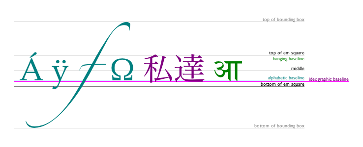
The keywords map to these alignment points as follows:
top
hanging
middle
alphabetic
ideographic
bottom
The text preparation algorithm is as follows. It takes
as input a string text, a
CanvasText object target, and an
optional length maxWidth. It returns an array of
glyph shapes, each positioned on a common coordinate space, and a
physical alignment whose value is one of
left, right, and center. (Most callers of this
algorithm ignore the physical alignment.)
If maxWidth was provided but is less than or equal to zero, return an empty array.
Replace all the space characters in text with U+0020 SPACE characters.
Let font be the current font of target, as given by that object's font attribute.
Apply the appropriate step from the following list to determine the value of direction:
Document and that
Document has a root element childDocument and that
Document has no root element childForm a hypothetical infinitely-wide CSS line box containing a single inline box containing the text text, with all the properties at their initial values except the 'font' property of the inline box set to font, the 'direction' property of the inline box set to direction, and the 'white-space' property set to 'pre'. [CSS]
If maxWidth was provided and the hypothetical width of the inline box in the hypothetical line box is greater than maxWidth CSS pixels, then change font to have a more condensed font (if one is available or if a reasonably readable one can be synthesized by applying a horizontal scale factor to the font) or a smaller font, and return to the previous step.
The anchor point is a point on the inline
box, and the physical alignment is one of the
values left, right, and center. These
variables are determined by the textAlign and textBaseline values as
follows:
Horizontal position:
textAlign is
lefttextAlign is
start and direction is
'ltr'textAlign is
end and direction is
'rtl'textAlign is
righttextAlign is
end and direction is
'ltr'textAlign is
start and direction is
'rtl'textAlign is
centerVertical position:
textBaseline is toptextBaseline is hangingtextBaseline is middletextBaseline is alphabetictextBaseline is ideographictextBaseline is bottomLet result be an array constructed by iterating over each glyph in the inline box from left to right (if any), adding to the array, for each glyph, the shape of the glyph as it is in the inline box, positioned on a coordinate space using CSS pixels with its origin is at the anchor point.
Return result, and, for callers that need it, physical alignment as the alignment value.
Each object implementing the CanvasPathMethods
interface has a path. A path has a list of zero or more subpaths.
Each subpath consists of a list of one or more points, connected by
straight or curved lines, and a flag indicating whether the subpath
is closed or not. A closed subpath is one where the last point of
the subpath is connected to the first point of the subpath by a
straight line. Subpaths with fewer than two points are ignored when
painting the path.
When an object implementing the CanvasPathMethods
interface is created, its path
must be initialized to zero subpaths.
moveTo(x, y)moveTo(x, y)Creates a new subpath with the given point.
closePath()closePath()Marks the current subpath as closed, and starts a new subpath with a point the same as the start and end of the newly closed subpath.
lineTo(x, y)lineTo(x, y)Adds the given point to the current subpath, connected to the previous one by a straight line.
quadraticCurveTo(cpx, cpy, x, y)quadraticCurveTo(cpx, cpy, x, y)Adds the given point to the current subpath, connected to the previous one by a quadratic Bézier curve with the given control point.
bezierCurveTo(cp1x, cp1y, cp2x, cp2y, x, y)bezierCurveTo(cp1x, cp1y, cp2x, cp2y, x, y)Adds the given point to the current subpath, connected to the previous one by a cubic Bézier curve with the given control points.
arcTo(x1, y1, x2, y2, radiusX [, radiusY, rotation ])arcTo(x1, y1, x2, y2, radius [, radiusY, rotation ])Adds an arc with the given control points and radius to the current subpath, connected to the previous point by a straight line.
If two radii are provided, the first controls the width of the arc's ellipse, and the second controls the height. If only one is provided, or if they are the same, the arc is from a circle. In the case of an ellipse, the rotation argument controls the anti-clockwise inclination of the ellipse relative to the x-axis.
Throws an IndexSizeError exception if the given
radius is negative.

arc(x, y, radius, startAngle, endAngle [, anticlockwise ] )arc(x, y, radius, startAngle, endAngle [, anticlockwise ] )Adds points to the subpath such that the arc described by the circumference of the circle described by the arguments, starting at the given start angle and ending at the given end angle, going in the given direction (defaulting to clockwise), is added to the path, connected to the previous point by a straight line.
Throws an IndexSizeError exception if the given
radius is negative.
ellipse(x, y, radiusX, radiusY, rotation, startAngle, endAngle, anticlockwise)ellipse(x, y, radiusX, radiusY, rotation, startAngle, endAngle, anticlockwise)Adds points to the subpath such that the arc described by the circumference of the ellipse described by the arguments, starting at the given start angle and ending at the given end angle, going in the given direction (defaulting to clockwise), is added to the path, connected to the previous point by a straight line.
Throws an IndexSizeError exception if the given
radius is negative.
rect(x, y, w, h)rect(x, y, w, h)Adds a new closed subpath to the path, representing the given rectangle.
The following methods allow authors to manipulate the paths of objects implementing the
CanvasPathMethods interface.
The points and lines added to an object's path by these methods must be
transformed according to the current transformation
matrix of the object implementing the
CanvasPathMethods interface before they are added to
the path.
All objects implementing the
CanvasPathMethods interface also implement the
CanvasTransformation interface, and thus have a current transformation
matrix.
The moveTo(x, y) method must
create a new subpath with the specified point as its first (and
only) point.
When the user agent is to ensure there is a subpath
for a coordinate (x, y) on a
path, the user agent must check to
see if the path has any subpaths,
and if it does not, then the user agent must create a new subpath
with the point (x, y) as its
first (and only) point, as if the moveTo() method had been
called.
The closePath()
method must do nothing if the object's path has no subpaths.
Otherwise, it must mark the last subpath as closed, create a new
subpath whose first point is the same as the previous subpath's
first point, and finally add this new subpath to the path.
If the last subpath had more than one point in its
list of points, then this is equivalent to adding a straight line
connecting the last point back to the first point, thus "closing"
the shape, and then repeating the last (possibly implied) moveTo() call.
New points and the lines connecting them are added to subpaths using the methods described below. In all cases, the methods only modify the last subpath in the object's path.
The lineTo(x, y) method must
ensure there is a subpath for (x, y) if the object's path
has no subpaths. Otherwise, it must connect the last point in the
subpath to the given point (x, y) using a straight line, and must then add the given
point (x, y) to the
subpath.
The quadraticCurveTo(cpx, cpy, x,
y) method must ensure there
is a subpath for (cpx,
cpy), and then must connect the last
point in the subpath to the given point (x, y) using a quadratic Bézier curve with control
point (cpx, cpy), and must
then add the given point (x, y) to the subpath. [BEZIER]
The bezierCurveTo(cp1x, cp1y, cp2x, cp2y, x, y) method must
ensure there is a subpath for (cp1x, cp1y), and then must
connect the last point in the subpath to the given point (x, y) using a cubic Bézier
curve with control points (cp1x, cp1y) and (cp2x, cp2y). Then, it must add the point (x, y) to the subpath. [BEZIER]
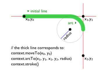
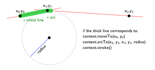
The arcTo(x1, y1, x2,
y2, radiusX, radiusY, rotation)
method must first ensure there is a subpath for (x1, y1).
Then, the behavior depends on the arguments and the last point in
the subpath, as described below.
Negative values for radiusX or radiusY must cause the implementation to throw an
IndexSizeError exception. If radiusY is omitted, user agents must act as if it had
the same value as radiusX.
Let the point (x0, y0) be the last point in the subpath.
If the point (x0, y0) is equal to the point (x1, y1), or if the point (x1, y1) is equal to the point (x2, y2), or if both radiusX and radiusY are zero, then the method must add the point (x1, y1) to the subpath, and connect that point to the previous point (x0, y0) by a straight line.
Otherwise, if the points (x0, y0), (x1, y1), and (x2, y2) all lie on a single straight line, then the method must add the point (x1, y1) to the subpath, and connect that point to the previous point (x0, y0) by a straight line.
Otherwise, let The Arc be the shortest arc given by circumference of the ellipse that has radius radiusX on the major axis and radius radiusY on the minor axis, and whose semi-major axis is rotated rotation radians anti-clockwise from the positive x-axis, and that has one point tangent to the half-infinite line that crosses the point (x0, y0) and ends at the point (x1, y1), and that has a different point tangent to the half-infinite line that ends at the point (x1, y1) and crosses the point (x2, y2). The points at which this ellipse touches these two lines are called the start and end tangent points respectively. The method must connect the point (x0, y0) to the start tangent point by a straight line, adding the start tangent point to the subpath, and then must connect the start tangent point to the end tangent point by The Arc, adding the end tangent point to the subpath.
The arc(x, y, radius,
startAngle, endAngle, anticlockwise) and ellipse(x,
y, radiusX, radiusY, rotation, startAngle, endAngle, anticlockwise) methods draw arcs.
The arc() method is
equivalent to the ellipse() method in the case
where the two radii are equal. When the arc() method is invoked, it must
act as if the ellipse()
method had been invoked with the radiusX and
radiusY arguments set to the value of the radius argument, the rotation
argument set to zero, and the other arguments set to the same values
as their identically named arguments on the arc() method.
When the ellipse()
method is invoked, it must proceed as follows. First, if the
object's path has any subpaths, then the method must add a straight
line from the last point in the subpath to the start point of the
arc. Then, it must add the start and end points of the arc to the
subpath, and connect them with an arc. The arc and its start and end
points are defined as follows:
Consider an ellipse that has its origin at (x, y), that has a major-axis radius radiusX and a minor-axis radius radiusY, and that is rotated about its origin such that its semi-major axis is inclined radius radians anti-clockwise from the x-axis. The points at startAngle and endAngle along this circle's circumference, measured in radians clockwise from the ellipse's semi-major axis, are the start and end points respectively.
If the anticlockwise argument false and endAngle-startAngle is equal to or greater than 2π, or, if the anticlockwise argument is true and startAngle-endAngle is equal to or greater than 2π, then the arc is the whole circumference of this ellipse.
Otherwise, the arc is the path along the circumference of this ellipse from the start point to the end point, going anti-clockwise if the anticlockwise argument is true, and clockwise otherwise. Since the points are on the ellipse, as opposed to being simply angles from zero, the arc can never cover an angle greater than 2π radians.
Negative values for radiusX or radiusY must cause the implementation to throw an
IndexSizeError exception.
The rect(x, y, w, h) method must create a new subpath
containing just the four points (x, y), (x+w,
y), (x+w, y+h),
(x, y+h), with those four points connected by straight
lines, and must then mark the subpath as closed. It must then create
a new subpath with the point (x, y) as the only point in the subpath.
Path objectsPath objects can be used to declare paths that are
then later used on CanvasRenderingContext2D objects. In
addition to many of the APIs described in earlier sections,
Path objects have methods to combine paths, and to add
text to paths.
Path([ element ])Creates a new Path object, optionally using a specific element for resolving relative keywords and sizes in font specifications.
addPathData(d)Adds to the path the path described by the argument, interpreted as SVG path data. [SVG]
addFill(path)addStroke(path)Adds to the path the path given by the argument.
addFillText(text, x, y [, maxWidth ])addFillText(text, path [, maxWidth ])addStrokeText(text, x, y [, maxWidth ])addStrokeText(text, path [, maxWidth ])Adds to the path a series of subpaths corresponding to the given text. If the arguments give a coordinate, the text is drawn horizontally at the given coordinates. If the arguments give a path, the text is drawn along the path. If a maximum width is provided, the text will be scaled to fit that width if necessary.
Each Path object has a path scope node.
The Path() constructor,
when invoked, must return a newly created Path object.
If the constructor was passed an argument, then the
Path object's path scope node is that
element. Otherwise, the object's path scope node is
the Document object of the active
document of the browsing context of the
Window object on which the interface object of the
invoked constructor is found.
The addPathData(d) method must run the following steps:
Parse and interpret the d argument according to the SVG specification's rules for path data, thus obtaining an SVG path. [SVG]
If this failed in some way, then throw a
SyntaxError exception, and abort these steps.
Transform all the coordinates and lines in the SVG path by
the current
transformation matrix of the Path
object.
Let (x, y) be the last point in the SVG path.
Add all the subpaths in the SVG path, if any, to the
Path object.
Create a new subpath in the Path object with
(x, y) as the only point in
the subpath.
The addFill(b) method, when invoked on a
Path object a, must run the
following steps:
If the Path object b has
no subpaths, abort these steps.
Create a copy of all the subpaths in b. Let this copy be known as c.
Transform all the coordinates and lines in c by the current transformation matrix of a.
Let (x, y) be the last point in the last subpath of c.
Add all the subpaths in c to a.
Create a new subpath in a with (x, y) as the only point in the subpath.
The addStroke(b) method, when invoked on a
Path object a, must run the
following steps:
If the Path object b has
no subpaths, abort these steps.
Create a copy of all the subpaths in b. Let this copy be known as c.
Transform all the coordinates and lines in c by the current transformation matrix of a.
Create a new list of subpaths d,
consisting of the subpaths necessary to describe the result of
tracing the subpaths in c, in the same order,
while applying the line styles of a (the lineWidth, lineCap, lineJoin, and (if
appropriate) miterLimit attributes).
Subpaths in d must wind clockwise, regardless
of the direction of paths in c.
Let (x, y) be the last point in the last subpath of d.
Add all the subpaths in d to a.
Create a new subpath in a with (x, y) as the only point in the subpath.
The addFillText() and
addStrokeText()
methods each come in two variants: one rendering text at a given
coordinate, and one rendering text along a given path. In both
cases, a maximum width can optionally be provided.
When one of the addFillText() and addStrokeText() variants
that take as argument an (x, y) coordinate is invoked, the method must run the
following algorithm:
Run the text preparation algorithm, passing it
text, the Path object, and, if the
maxWidth argument was provided, that argument.
Let glyphs be the result.
Move all the shapes in glyphs to the right by x CSS pixels and down by y CSS pixels.
Let glyph subpaths be a list of subpaths describing the shapes given in glyphs, with each CSS pixel in the coordinate space of glyphs mapped to one coordinate space unit in glyph subpaths. Subpaths in glyph subpaths must wind clockwise, regardless of how the user agent's font subsystem renders fonts and regardless of how the fonts themselves are defined.
If the method is addStrokeText(),
replace glyph subpaths by a new list of
subpaths consisting of the subpaths necessary to describe the
result of tracing the subpaths added to glyph
subpaths in the preview step, in the same order, while
applying the line styles of the Path object (the lineWidth, lineCap, lineJoin, and (if
appropriate) miterLimit attributes).
These subpaths in glyph subpaths must also all
wind clockwise.
Transform all the coordinates and lines in glyph subpaths by the current transformation
matrix of the Path object.
Let (xfinal, yfinal) be the last point in the last subpath of glyph subpaths.
Add all the subpaths in glyph
subpaths to the Path object.
Create a new subpath in the Path object with
(xfinal, yfinal) as the only point in the
subpath.
When one of the addFillText() and addStrokeText() variants
that take as argument a Path object is invoked, the
method must run the following algorithm:
Let target be the Path
object on which the method was invoked.
Let path be the Path object
that was provided in the method's arguments.
Run the text preparation algorithm, passing it text, target, and, if the maxWidth argument was provided, that argument. Let glyphs be the resulting array, and physical alignment be the resulting alignment value.
Let width be the aggregate length of all the subpaths in path, including the distances from the last point of each closed subpath to the first point of that subpath.
Define L to be a linear coordinate line for of all the subpaths in path, with additional lines drawn between the last point and the first point of each closed subpath, such that the first point of the first subpath is defined as point 0, and the last point of the last subpath, if the last subpath is not closed, or the second occurrence first point of that subpath, if it is closed, is defined as point width.
Let offset be determined according to the appropriate step below:
Move all the shapes in glyphs to the right by offset CSS pixels.
For each glyph glyph in the glyphs array, run these substeps:
Let dx be the x-coordinate of the horizontal center of the bounding box of the shape described by glyph, in CSS pixels.
If dx is negative or greater than width, skip the remainder of these substeps for this glyph.
Recast dx to coordinate spaces units in path. (This just changes the dimensionality of dx, not its numeric value.)
Find the point p on path (or implied closing lines in path) that corresponds to the position dx on the coordinate line L.
Let θ be the clockwise angle from the positive x-axis to the side of the line that is tangential to path at the point p that is going in the same direction as the line at point p.
Rotate the shape described by glyph clockwise by θ about the point that is at the dx coordinate horizontally and the zero coordinate vertically.
Let (x, y) be the coordinate of the point p.
Move the shape described by glyph to the right by x and down by y.
Let glyph subpaths be a list of subpaths describing the shape given in glyph, with each CSS pixel in the coordinate space of glyph mapped to one coordinate space unit in glyph subpaths. Subpaths in glyph subpaths must wind clockwise, regardless of how the user agent's font subsystem renders fonts and regardless of how the fonts themselves are defined.
If the method is addStrokeText(),
replace glyph subpaths by a new list of
subpaths consisting of the subpaths necessary to describe the
result of tracing the subpaths added to glyph
subpaths in the preview step, in the same order, while
applying the line styles of the target object
(the lineWidth,
lineCap, lineJoin, and (if
appropriate) miterLimit attributes).
These subpaths in glyph subpaths must also
all wind clockwise.
Transform all the coordinates and lines in glyph subpaths by the current transformation matrix of target.
Let (xfinal, yfinal) be the last point in the last subpath of glyph subpaths. (This coordinate is only used if this is the last glyph processed.)
Add all the subpaths in glyph subpaths to target.
Create a new subpath in the Path object with
(xfinal, yfinal) as the only point in the
subpath.
fillStyle [ = value ]Returns the current style used for filling shapes.
Can be set, to change the fill style.
The style can be either a string containing a CSS color, or a
CanvasGradient or CanvasPattern
object. Invalid values are ignored.
strokeStyle [ = value ]Returns the current style used for stroking shapes.
Can be set, to change the stroke style.
The style can be either a string containing a CSS color, or a
CanvasGradient or CanvasPattern
object. Invalid values are ignored.
The fillStyle
attribute represents the color or style to use inside shapes, and
the strokeStyle
attribute represents the color or style to use for the lines around
the shapes.
Both attributes can be either strings,
CanvasGradients, or CanvasPatterns. On
setting, strings must be parsed as CSS <color> values and the color
assigned, and CanvasGradient and
CanvasPattern objects must be assigned themselves. [CSSCOLOR] If the value is a string but
cannot be parsed as a CSS <color> value, or is
neither a string, a CanvasGradient, nor a
CanvasPattern, then it must be ignored, and the
attribute must retain its previous value.
When set to a CanvasPattern or
CanvasGradient object, the assignment is
live, meaning that changes made to the object after the
assignment do affect subsequent stroking or filling of shapes.
On getting, if the value is a color, then the serialization of the color
must be returned. Otherwise, if it is not a color but a
CanvasGradient or CanvasPattern, then the
respective object must be returned. (Such objects are opaque and
therefore only useful for assigning to other attributes or for
comparison to other gradients or patterns.)
The serialization of a color for a color value is a
string, computed as follows: if it has alpha equal to 1.0, then the
string is a lowercase six-digit hex value, prefixed with a "#"
character (U+0023 NUMBER SIGN), with the first two digits
representing the red component, the next two digits representing the
green component, and the last two digits representing the blue
component, the digits being in the range 0-9 a-f (U+0030 to U+0039
and U+0061 to U+0066). Otherwise, the color value has alpha less
than 1.0, and the string is the color value in the CSS rgba() functional-notation format: the literal
string rgba (U+0072 U+0067 U+0062 U+0061)
followed by a U+0028 LEFT PARENTHESIS, a base-ten integer in the
range 0-255 representing the red component (using digits 0-9, U+0030
to U+0039, in the shortest form possible), a literal U+002C COMMA
and U+0020 SPACE, an integer for the green component, a comma and a
space, an integer for the blue component, another comma and space, a
U+0030 DIGIT ZERO, if the alpha value is greater than zero then a
U+002E FULL STOP (representing the decimal point), if the alpha
value is greater than zero then one or more digits in the range 0-9
(U+0030 to U+0039) representing the fractional part of the alpha, and
finally a U+0029 RIGHT PARENTHESIS. User agents must express the
fractional part of the alpha value, if any, with the level of
precision necessary for the alpha value, when reparsed, to be
interpreted as the same alpha value.
When the context is created, the fillStyle and strokeStyle attributes
must initially have the string value #000000.
When the value is a color, it must not be affected by the transformation matrix when used to draw on the canvas.
There are two types of gradients, linear gradients and radial
gradients, both represented by objects implementing the opaque
CanvasGradient interface.
Once a gradient has been created (see below), stops are placed along it to define how the colors are distributed along the gradient. The color of the gradient at each stop is the color specified for that stop. Between each such stop, the colors and the alpha component must be linearly interpolated over the RGBA space without premultiplying the alpha value to find the color to use at that offset. Before the first stop, the color must be the color of the first stop. After the last stop, the color must be the color of the last stop. When there are no stops, the gradient is transparent black.
addColorStop(offset, color)Adds a color stop with the given color to the gradient at the given offset. 0.0 is the offset at one end of the gradient, 1.0 is the offset at the other end.
Throws an IndexSizeError exception if the offset
is out of range. Throws a SyntaxError exception if the
color cannot be parsed.
createLinearGradient(x0, y0, x1, y1)Returns a CanvasGradient object that represents a
linear gradient that paints along the line given by the
coordinates represented by the arguments.
If any of the arguments are not finite numbers, throws a
NotSupportedError exception.
createRadialGradient(x0, y0, r0, x1, y1, r1)Returns a CanvasGradient object that represents a
radial gradient that paints along the cone given by the circles
represented by the arguments.
If any of the arguments are not finite numbers, throws a
NotSupportedError exception. If either of the radii
are negative, throws an IndexSizeError exception.
The addColorStop(offset, color)
method on the CanvasGradient interface adds a new stop
to a gradient. If the offset is less than 0,
greater than 1, infinite, or NaN, then an
IndexSizeError exception must be thrown. If the color cannot be parsed as a CSS <color>
value, then a SyntaxError exception must be
thrown. Otherwise, the gradient must have a new stop placed, at
offset offset relative to the whole gradient,
and with the color obtained by parsing color as
a CSS <color> value. If multiple stops are added at the same
offset on a gradient, they must be placed in the order added, with
the first one closest to the start of the gradient, and each
subsequent one infinitesimally further along towards the end point
(in effect causing all but the first and last stop added at each
point to be ignored).
The createLinearGradient(x0, y0, x1,
y1) method takes four arguments
that represent the start point (x0, y0) and end point (x1, y1) of the gradient. If any of the arguments to createLinearGradient()
are infinite or NaN, the method must throw a
NotSupportedError exception. Otherwise, the method must
return a linear CanvasGradient initialized with the
specified line.
Linear gradients must be rendered such that all points on a line perpendicular to the line that crosses the start and end points have the color at the point where those two lines cross (with the colors coming from the interpolation and extrapolation described above). The points in the linear gradient must be transformed as described by the current transformation matrix when rendering.
If x0 = x1 and y0 = y1, then the linear gradient must paint nothing.
The createRadialGradient(x0, y0, r0,
x1, y1, r1) method takes six arguments, the
first three representing the start circle with origin (x0, y0) and radius r0, and the last three representing the end circle
with origin (x1, y1) and
radius r1. The values are in coordinate space
units. If any of the arguments are infinite or NaN, a
NotSupportedError exception must be thrown. If either
of r0 or r1 are negative, an
IndexSizeError exception must be thrown. Otherwise,
the method must return a radial CanvasGradient
initialized with the two specified circles.
Radial gradients must be rendered by following these steps:
If x0 = x1 and y0 = y1 and r0 = r1, then the radial gradient must paint nothing. Abort these steps.
Let x(ω) = (x1-x0)ω + x0
Let y(ω) = (y1-y0)ω + y0
Let r(ω) = (r1-r0)ω + r0
Let the color at ω be the color at that position on the gradient (with the colors coming from the interpolation and extrapolation described above).
For all values of ω where r(ω) > 0, starting with the value of ω nearest to positive infinity and ending with the value of ω nearest to negative infinity, draw the circumference of the circle with radius r(ω) at position (x(ω), y(ω)), with the color at ω, but only painting on the parts of the canvas that have not yet been painted on by earlier circles in this step for this rendering of the gradient.
This effectively creates a cone, touched by the two circles defined in the creation of the gradient, with the part of the cone before the start circle (0.0) using the color of the first offset, the part of the cone after the end circle (1.0) using the color of the last offset, and areas outside the cone untouched by the gradient (transparent black).
The resulting radial gradient must then be transformed as described by the current transformation matrix when rendering.
Gradients must be painted only where the relevant stroking or filling effects requires that they be drawn.
Patterns are represented by objects implementing the opaque
CanvasPattern interface.
createPattern(image, repetition)Returns a CanvasPattern object that uses the given image
and repeats in the direction(s) given by the repetition argument.
The allowed values for repetition are repeat (both directions), repeat-x (horizontal only), repeat-y (vertical only), and no-repeat (neither). If the repetition argument is empty, the value repeat is used.
If the image has no image data, throws an
InvalidStateError exception. If the second argument
isn't one of the allowed values, throws a SyntaxError
exception. If the image isn't yet fully decoded, then the method
returns null.
To create objects of this type, the createPattern(image, repetition)
method is used. The first argument gives the image to use as the
pattern (either an HTMLImageElement,
HTMLCanvasElement, or HTMLVideoElement
object). Modifying this image after calling the createPattern() method
must not affect the pattern. The second argument must be a string
with one of the following values: repeat,
repeat-x, repeat-y,
no-repeat. If the empty string is specified,
repeat must be assumed. If an unrecognized value
is given, then the user agent must throw a SyntaxError
exception. User agents must recognize the four values described above
exactly (e.g. they must not do case folding). Except as specified
below, the method must return a CanvasPattern object
suitably initialized.
The image argument is an instance of either
HTMLImageElement, HTMLCanvasElement, or
HTMLVideoElement.
If the image argument is an
HTMLImageElement object that is not fully decodable, or if the image argument is an HTMLVideoElement
object whose readyState
attribute is either HAVE_NOTHING or HAVE_METADATA, then the
implementation must return null.
If the image argument is an
HTMLCanvasElement object with either a horizontal
dimension or a vertical dimension equal to zero, then the
implementation must throw an InvalidStateError
exception.
Patterns must be painted so that the top left of the first image
is anchored at the origin of the coordinate space, and images are
then repeated horizontally to the left and right, if the
repeat-x string was specified, or vertically up and
down, if the repeat-y string was specified, or in all
four directions all over the canvas, if the repeat
string was specified, to create the repeated pattern that is used
for rendering. The images are not scaled by this process; one CSS
pixel of the image must be painted on one coordinate space unit in
generating the repeated pattern. When rendered, however, patterns
must actually be painted only where the stroking or filling effect
requires that they be drawn, and the repeated pattern must be
affected by the current transformation matrix. Pixels not covered by
the repeating pattern (if the repeat string was not
specified) must be transparent black.
If the original image data is a bitmap image, the value painted at a point in the area of the repetitions is computed by filtering the original image data. The user agent may use any filtering algorithm (for example bilinear interpolation or nearest-neighbor). When the filtering algorithm requires a pixel value from outside the original image data, it must instead use the value from wrapping the pixel's coordinates to the original image's dimensions. (That is, the filter uses 'repeat' behavior, regardless of the value of repetition.)
When the createPattern() method
is passed an animated image as its image
argument, the user agent must use the poster frame of the animation,
or, if there is no poster frame, the first frame of the
animation.
When the image argument is an
HTMLVideoElement, then the frame at the current
playback position must be used as the source image, and the
source image's dimensions must be the intrinsic width and
intrinsic height
of the media resource (i.e. after any aspect-ratio
correction has been applied).
If a radial gradient or repeated pattern is used when the transformation matrix is singular, the resulting style must be transparent black (otherwise the gradient or pattern would be collapsed to a point or line, leaving the other pixels undefined). Linear gradients and solid colors always define all points even with singular tranformation matrices.
There are three methods that immediately draw rectangles to the bitmap. They each take four arguments; the first two give the x and y coordinates of the top left of the rectangle, and the second two give the width w and height h of the rectangle, respectively.
The current transformation matrix must be applied to the following four coordinates, which form the path that must then be closed to get the specified rectangle: (x, y), (x+w, y), (x+w, y+h), (x, y+h).
Shapes are painted without affecting the current default path,
and are subject to the clipping
region, and, with the exception of clearRect(), also shadow effects, global alpha, and global composition
operators.
clearRect(x, y, w, h)Clears all pixels on the canvas in the given rectangle to transparent black.
fillRect(x, y, w, h)Paints the given rectangle onto the canvas, using the current fill style.
strokeRect(x, y, w, h)Paints the box that outlines the given rectangle onto the canvas, using the current stroke style.
The clearRect(x, y, w, h) method must clear the pixels in the
specified rectangle that also intersect the current clipping region
to a fully transparent black, erasing any previous image. If either
height or width are zero, this method has no effect.
The fillRect(x, y, w, h) method must paint the specified
rectangular area using the fillStyle. If either height
or width are zero, this method has no effect.
The strokeRect(x, y, w, h) method must stroke the specified
rectangle's path using the strokeStyle, lineWidth, lineJoin, and (if
appropriate) miterLimit attributes. If
both height and width are zero, this method has no effect, since
there is no path to stroke (it's a point). If only one of the two is
zero, then the method will draw a line instead (the path for the
outline is just a straight line along the non-zero dimension).
fillText(text, x, y [, maxWidth ] )strokeText(text, x, y [, maxWidth ] )Fills or strokes (respectively) the given text at the given position. If a maximum width is provided, the text will be scaled to fit that width if necessary.
measureText(text)Returns a TextMetrics object with the metrics of the given text in the current font.
widthReturns the advance width of the text that was passed to the
measureText()
method.
The CanvasRenderingContext2D interface provides the
following methods for rendering text directly to the canvas.
The fillText() and
strokeText()
methods take three or four arguments, text, x, y, and optionally maxWidth, and render the given text at the given (x, y) coordinates ensuring that the text isn't wider
than maxWidth if specified, using the current
font, textAlign, and textBaseline
values. Specifically, when the methods are called, the user agent
must run the following steps:
Run the text preparation algorithm, passing it
text, the CanvasRenderingContext2D
object, and, if the maxWidth argument was
provided, that argument. Let glyphs be the
result.
Move all the shapes in glyphs to the right by x CSS pixels and down by y CSS pixels.
Paint the shapes given in glyphs, as transformed by the current transformation matrix, with each CSS pixel in the coordinate space of glyphs mapped to one coordinate space unit.
For fillText(),
fillStyle must be
applied to the shapes and strokeStyle must be
ignored. For strokeText(), the reverse
holds and strokeStyle must be
applied to the shape outlines, along with the lineWidth, lineCap, lineJoin, and (if
appropriate) miterLimit attributes,
and fillStyle must
be ignored.
These shapes are painted without affecting the current path, and are subject to shadow effects, global alpha, the clipping region, and global composition operators.
The measureText()
method takes one argument, text. When the method
is invoked, the user agent must replace all the space characters in text with
U+0020 SPACE characters, and then must form a hypothetical
infinitely-wide CSS line box containing a single inline box
containing the text text, with all the
properties at their initial values except the 'white-space' property
of the inline element set to 'pre' and the 'font' property of the
inline element set to the current font of the context as given by
the font attribute, and
must then create a new TextMetrics object with its
width attribute set to
the width of that inline box, in CSS pixels.
If doing these measurements requires using a font that has an
origin that is not the same as that of the Document object that
owns the canvas element (even if "using a font" means
just checking if that font has a particular glyph in it before
falling back to another font), then the method must throw a
SecurityError exception.
Otherwise, it must return the new TextMetrics object.
[CSS]
The TextMetrics interface is used for the objects
returned from measureText(). It has one
attribute, width, which is set
by the measureText()
method.
Glyphs rendered using fillText() and strokeText() can spill out
of the box given by the font size (the em square size) and the width
returned by measureText() (the text
width). This version of the specification does not provide a way to
obtain the bounding box dimensions of the text. If the text is to be
rendered and removed, care needs to be taken to replace the entire
area of the canvas that the clipping region covers, not just the box
given by the em square height and measured text width.
A future version of the 2D context API may provide a way to render fragments of documents, rendered using CSS, straight to the canvas. This would be provided in preference to a dedicated way of doing multiline layout.
The context always has a current default path. There is only one current default path, it is not part of the drawing state. The current default path is a path, as described in the previous section.
beginPath()Resets the current default path.
fill()fill(path)Fills the subpaths of the current default path or the given path with the current fill style.
stroke()stroke(path)Strokes the subpaths of the current default path or the given path with the current stroke style.
drawSystemFocusRing(element)drawSystemFocusRing(path, element)If the given element is focused, draws a focus ring around the current default path or hte given path, following the platform conventions for focus rings.
drawCustomFocusRing(element)drawCustomFocusRing(path, element)If the given element is focused, and the user has configured his system to draw focus rings in a particular manner (for example, high contrast focus rings), draws a focus ring around the current default path or the given path and returns false.
Otherwise, returns true if the given element is focused, and false otherwise. This can thus be used to determine when to draw a focus ring (see the example below).
scrollPathIntoView()scrollPathIntoView(path)Scrolls the current default path into view. This is especially useful on devices with small screens, where the whole canvas might not be visible at once.
clip()clip(path)Further constrains the clipping region to the current default path.
isPointInPath(x, y)isPointInPath(path, x, y)Returns true if the given point is in the current default path.
The beginPath()
method must empty the list of subpaths in the context's current
default path so that the it once again has zero subpaths.
Where the following method definitions use the term intended
path, it means the Path argument, if one was
provided, or the current default path otherwise.
When the intended path is a Path object, the
coordinates of its subpaths must be transformed according to the
CanvasRenderingContext2D object's current transformation
matrix when used by these methods (without affecting the
Path object itself). When the intended path is the
current default path, it is not affected by the transform, (This is
because transformations already affect the current default path when
it is constructed, so applying it when it is painted as well would
result in a double transformation.)
The fill()
method must fill all the subpaths of the intended path, using fillStyle, and using the
non-zero winding number rule. Open subpaths must be implicitly
closed when being filled (without affecting the actual
subpaths).
Thus, if two overlapping but otherwise independent subpaths have opposite windings, they cancel out and result in no fill. If they have the same winding, that area just gets painted once.
The stroke() method
must calculate the strokes of all the subpaths of the intended path,
using the lineWidth,
lineCap, lineJoin, and (if
appropriate) miterLimit attributes, and
then fill the combined stroke area using the strokeStyle attribute.
Since the subpaths are all stroked as one, overlapping parts of the paths in one stroke operation are treated as if their union was what was painted.
The stroke style is affected by the transformation during painting, even if the intended path is the current default path.
Paths, when filled or stroked, must be painted without affecting
the current default path or any Path objects, and must
be subject to shadow effects, global alpha, the clipping region, and global composition
operators. (The effect of transformations is described above
and varies based on which path is being used.)
Zero-length line segments must be pruned before stroking a path. Empty subpaths must be ignored.
The drawSystemFocusRing(element) method, when invoked, must run
the following steps:
If element is not focused or is not a descendant of the element with whose context the method is associated, then abort these steps.
If the user has requested the use of particular focus rings (e.g. high-contrast focus rings), or if the element would have a focus ring drawn around it, then draw a focus ring of the appropriate style along the intended path, following platform conventions, and abort these steps.
Some platforms only draw focus rings around
elements that have been focused from the keyboard, and not those
focused from the mouse. Other platforms simply don't draw focus
rings around some elements at all unless relevant accessibility
features are enabled. This API is intended to follow these
conventions. User agents that implement distinctions based on the
manner in which the element was focused are encouraged to classify
focus driven by the focus() method
based on the kind of user interaction event from which the call
was triggered (if any).
The focus ring should not be subject to the shadow effects, the global alpha, or the global composition operators, but should be subject to the clipping region. (The effect of transformations is described above and varies based on which path is being used.)
Optionally, inform the user that the focus is at the location given by the intended path. User agents may wait until the next time the event loop reaches its "update the rendering" step to optionally inform the user.
The drawCustomFocusRing(element) method, when invoked, must run
the following steps:
If element is not focused or is not a descendant of the element with whose context the method is associated, then return false and abort these steps.
If the user has requested the use of particular focus rings (e.g. high-contrast focus rings), then draw a focus ring of the appropriate style along the intended path, return false, and abort these steps.
The focus ring should not be subject to the shadow effects, the global alpha, or the global composition operators, but should be subject to the clipping region. (The effect of transformations is described above and varies based on which path is being used.)
Optionally, inform the user that the focus is at the location given by the intended path. User agents may wait until the next time the event loop reaches its "update the rendering" step to optionally inform the user.
Return true.
The scrollPathIntoView()
method, when invoked, must run the following steps:
Let the specified rectangle be the rectangle of the bounding box of the intended path.
Let notional child be a hypothetical
element that is a rendered child of the canvas element
whose dimensions are those of the specified
rectangle.
Scroll notional child into view with the align to top flag set.
Optionally, inform the user that the caret and/or selection cover the specified rectangle of the canvas. User agents may wait until the next time the event loop reaches its "update the rendering" step to optionally inform the user.
"Inform the user", as used in this section, could mean calling a system accessibility API, which would notify assistive technologies such as magnification tools. To properly drive magnification based on a focus change, a system accessibility API driving a screen magnifier needs the bounds for the newly focused object. The methods above are intended to enable this by allowing the user agent to report the bounding box of the path used to render the focus ring as the bounds of the element element passed as an argument, if that element is focused, and the bounding box of the area to which the user agent is scrolling as the bounding box of the current selection.
The clip()
method must create a new clipping region by calculating
the intersection of the current clipping region and the area
described by the intended path, using the non-zero winding number
rule. Open subpaths must be implicitly closed when computing the
clipping region, without affecting the actual subpaths. The new
clipping region replaces the current clipping region.
When the context is initialized, the clipping region must be set to the rectangle with the top left corner at (0,0) and the width and height of the coordinate space.
The isPointInPath(x, y) method must
return true if the point given by the x and y coordinates passed to the method, when treated as
coordinates in the canvas coordinate space unaffected by the current
transformation, is inside the intended path as determined by the
non-zero winding number rule; and must return false otherwise.
Points on the path itself must be considered to be inside the path.
If either of the arguments is infinite or NaN, then the method must
return false.
This canvas element has a couple of checkboxes. The
path-related commands are highlighted:
<canvas height=400 width=750>
 <label><input type=checkbox id=showA> Show As</label>
 <label><input type=checkbox id=showB> Show Bs</label>
 <!-- ... -->
</canvas>
<script>
 function drawCheckbox(context, element, x, y, paint) {
   context.save();
   context.font = '10px sans-serif';
   context.textAlign = 'left';
   context.textBaseline = 'middle';
   var metrics = context.measureText(element.labels[0].textContent);
   if (paint) {
     context.beginPath();
     context.strokeStyle = 'black';
     context.rect(x-5, y-5, 10, 10);
     context.stroke();
     if (element.checked) {
       context.fillStyle = 'black';
       context.fill();
     }
     context.fillText(element.labels[0].textContent, x+5, y);
   }
   context.beginPath();
   context.rect(x-7, y-7, 12 + metrics.width+2, 14);
   if (paint && context.drawCustomFocusRing(element)) {
     context.strokeStyle = 'silver';
     context.stroke();
   }
   context.restore();
 }
 function drawBase() { /* ... */ }
 function drawAs() { /* ... */ }
 function drawBs() { /* ... */ }
 function redraw() {
   var canvas = document.getElementsByTagName('canvas')[0];
   var context = canvas.getContext('2d');
   context.clearRect(0, 0, canvas.width, canvas.height);
   drawCheckbox(context, document.getElementById('showA'), 20, 40, true);
   drawCheckbox(context, document.getElementById('showB'), 20, 60, true);
   drawBase();
   if (document.getElementById('showA').checked)
     drawAs();
   if (document.getElementById('showB').checked)
     drawBs();
 }
 function processClick(event) {
   var canvas = document.getElementsByTagName('canvas')[0];
   var context = canvas.getContext('2d');
   var x = event.clientX;
   var y = event.clientY;
   var node = event.target;
   while (node) {
     x -= node.offsetLeft - node.scrollLeft;
     y -= node.offsetTop - node.scrollTop;
     node = node.offsetParent;
   }
   drawCheckbox(context, document.getElementById('showA'), 20, 40, false);
   if (context.isPointInPath(x, y))
     document.getElementById('showA').checked = !(document.getElementById('showA').checked);
   drawCheckbox(context, document.getElementById('showB'), 20, 60, false);
   if (context.isPointInPath(x, y))
     document.getElementById('showB').checked = !(document.getElementById('showB').checked);
   redraw();
 }
 document.getElementsByTagName('canvas')[0].addEventListener('focus', redraw, true);
 document.getElementsByTagName('canvas')[0].addEventListener('blur', redraw, true);
 document.getElementsByTagName('canvas')[0].addEventListener('change', redraw, true);
 document.getElementsByTagName('canvas')[0].addEventListener('click', processClick, false);
 redraw();
</script>
To draw images onto the canvas, the drawImage method
can be used.
This method can be invoked with three different sets of arguments:
drawImage(image, dx, dy)
drawImage(image, dx, dy, dw, dh)
drawImage(image, sx, sy, sw, sh, dx, dy, dw, dh)
Each of those three can take either an
HTMLImageElement, an HTMLCanvasElement, or
an HTMLVideoElement for the image
argument.
drawImage(image, dx, dy)drawImage(image, dx, dy, dw, dh)drawImage(image, sx, sy, sw, sh, dx, dy, dw, dh)Draws the given image onto the canvas. The arguments are interpreted as follows:
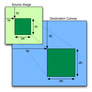
If the first argument isn't an img,
canvas, or video element, throws a
TypeMismatchError exception. If the image has no
image data, throws an InvalidStateError exception. If
the one of the source rectangle dimensions is zero, throws an
IndexSizeError exception. If the image isn't yet
fully decoded, then nothing is drawn.
If not specified, the dw and dh arguments must default to the values of sw and sh, interpreted such that
one CSS pixel in the image is treated as one unit in the canvas
coordinate space. If the sx, sy, sw, and sh arguments are omitted, they must default to 0, 0,
the image's intrinsic width in image pixels, and the image's
intrinsic height in image pixels, respectively. If the image has no
intrinsic dimensions, the concrete object size must be used
instead, as determined using the CSS "Concrete
Object Size Resolution" algorithm, with the specified
size having neither a definite width nor height, nor any
additional contraints, the object's intrinsic properties being those
of the image argument, and the default object
size being the size of the canvas element. [CSSIMAGES]
The image argument is an instance of either
HTMLImageElement, HTMLCanvasElement, or
HTMLVideoElement.
If the image argument is an
HTMLImageElement object that is not fully decodable, or if the image argument is an HTMLVideoElement
object whose readyState
attribute is either HAVE_NOTHING or HAVE_METADATA, then the
implementation must return without drawing anything.
If the image argument is an
HTMLCanvasElement object with either a horizontal
dimension or a vertical dimension equal to zero, then the
implementation must throw an InvalidStateError
exception.
The source rectangle is the rectangle whose corners are the four points (sx, sy), (sx+sw, sy), (sx+sw, sy+sh), (sx, sy+sh).
If one of the sw or sh
arguments is zero, the implementation must throw an
IndexSizeError exception.
The destination rectangle is the rectangle whose corners are the four points (dx, dy), (dx+dw, dy), (dx+dw, dy+dh), (dx, dy+dh).
When the source rectangle is outside the source image, it must be clipped to the source image, and the destination rectangle must be clipped in the same proportion.
When drawImage() is
invoked, the region of the image specified by the source rectangle
must be painted on the region of the canvas specified by the
destination rectangle, after applying the current transformation
matrix to the points of the destination rectangle.
The original image data of the source image must be used, not the
image as it is rendered (e.g. width and height attributes on the source
element have no effect). The image data must be processed in the
original direction, even if the dimensions given are negative.
This specification does not define the algorithm to use when scaling the image, if necessary.
When a canvas is drawn onto itself, the drawing model requires the source to be copied before the image is drawn back onto the canvas, so it is possible to copy parts of a canvas onto overlapping parts of itself.
If the original image data is a bitmap image, the value painted at a point in the destination rectangle is computed by filtering the original image data. The user agent may use any filtering algorithm (for example bilinear interpolation or nearest-neighbor). When the filtering algorithm requires a pixel value from outside the original image data, it must instead use the value from the nearest edge pixel. (That is, the filter uses 'clamp-to-edge' behavior.)
When the drawImage() method
is passed an animated image as its image
argument, the user agent must use the poster frame of the animation,
or, if there is no poster frame, the first frame of the
animation.
When the image argument is an
HTMLVideoElement, then the frame at the current
playback position must be used as the source image, and the
source image's dimensions must be the intrinsic width and
intrinsic height
of the media resource (i.e. after any aspect-ratio
correction has been applied).
Images are painted without affecting the current path, and are subject to shadow effects, global alpha, the clipping region, and global composition operators.
createImageData(sw, sh)Returns an ImageData object with the given
dimensions in CSS pixels (which might map to a different number of
actual device pixels exposed by the object itself). All the pixels
in the returned object are transparent black.
createImageData(imagedata)Returns an ImageData object with the same
dimensions as the argument. All the pixels in the returned object
are transparent black.
getImageData(sx, sy, sw, sh)Returns an ImageData object containing the image
data for the given rectangle of the canvas.
Throws a NotSupportedError exception if any of the
arguments are not finite. Throws an IndexSizeError
exception if the either of the width or height arguments are
zero.
widthheightReturns the actual dimensions of the data in the ImageData object, in device pixels.
dataReturns the one-dimensional array containing the data in RGBA order, as integers in the range 0 to 255.
putImageData(imagedata, dx, dy [, dirtyX, dirtyY, dirtyWidth, dirtyHeight ])Paints the data from the given ImageData object
onto the canvas. If a dirty rectangle is provided, only the pixels
from that rectangle are painted.
The globalAlpha
and globalCompositeOperation
attributes, as well as the shadow attributes, are ignored for the
purposes of this method call; pixels in the canvas are replaced
wholesale, with no composition, alpha blending, no shadows,
etc.
Throws a NotSupportedError exception if any of the
arguments are not finite.
The createImageData()
method is used to instantiate new blank ImageData
objects. When the method is invoked with two arguments sw and sh, it must return an
ImageData object representing a rectangle with a width
in CSS pixels equal to the absolute magnitude of sw and a height in CSS pixels equal to the absolute
magnitude of sh. When invoked with a single imagedata argument, it must return an
ImageData object representing a rectangle with the same
dimensions as the ImageData object passed as the
argument. The ImageData object returned must be filled
with transparent black.
The getImageData(sx, sy, sw,
sh) method must,
if the canvas element's origin-clean flag is set
to false, throw a SecurityError exception; otherwise, it
must return an ImageData object representing the
underlying pixel data for the area of the canvas denoted by the
rectangle whose corners are the four points (sx,
sy), (sx+sw, sy), (sx+sw, sy+sh),
(sx, sy+sh), in canvas coordinate space units. Pixels
outside the canvas must be returned as transparent black. Pixels
must be returned as non-premultiplied alpha values.
If any of the arguments to createImageData() or
getImageData()
are infinite or NaN, the method must instead throw a
NotSupportedError exception. If either the sw or sh arguments are zero,
the method must instead throw an IndexSizeError
exception.
ImageData objects must be initialized so that their
width attribute
is set to w, the number of physical device
pixels per row in the image data, their height attribute is
set to h, the number of rows in the image data,
and their data
attribute is initialized to a Uint8ClampedArray object.
The Uint8ClampedArray object must use a Canvas
Pixel ArrayBuffer for its storage, and must have
a zero start offset and a length equal to the length of its storage,
in bytes. The Canvas Pixel ArrayBuffer
must contain the image data. At least one pixel's worth of image
data must be returned. [TYPEDARRAY]
A Canvas Pixel ArrayBuffer is an
ArrayBuffer that whose data is represented in
left-to-right order, row by row top to bottom, starting with the top
left, with each pixel's red, green, blue, and alpha components being
given in that order for each pixel. Each component of each device
pixel represented in this array must be in the range 0..255,
representing the 8 bit value for that component. The components must
be assigned consecutive indices starting with 0 for the top left
pixel's red component. [TYPEDARRAY]
The putImageData(imagedata, dx, dy, dirtyX, dirtyY, dirtyWidth, dirtyHeight) method writes data from
ImageData structures back to the canvas.
If any of the arguments to the method are infinite or NaN, the
method must throw a NotSupportedError exception.
When the last four arguments are omitted, they must be assumed to
have the values 0, 0, the width member of the imagedata structure, and the height member of the imagedata structure, respectively.
When invoked with arguments that do not, per the last few
paragraphs, cause an exception to be thrown, the putImageData() method
must act as follows:
Let dxdevice be the x-coordinate of the device pixel in the underlying pixel data of the canvas corresponding to the dx coordinate in the canvas coordinate space.
Let dydevice be the y-coordinate of the device pixel in the underlying pixel data of the canvas corresponding to the dy coordinate in the canvas coordinate space.
If dirtyWidth is negative, let dirtyX be dirtyX+dirtyWidth, and let dirtyWidth be equal to the absolute magnitude of dirtyWidth.
If dirtyHeight is negative, let dirtyY be dirtyY+dirtyHeight, and let dirtyHeight be equal to the absolute magnitude of dirtyHeight.
If dirtyX is negative, let dirtyWidth be dirtyWidth+dirtyX, and let dirtyX be zero.
If dirtyY is negative, let dirtyHeight be dirtyHeight+dirtyY, and let dirtyY be zero.
If dirtyX+dirtyWidth is greater than the width attribute of the imagedata argument, let dirtyWidth be the value of that width attribute, minus the
value of dirtyX.
If dirtyY+dirtyHeight is greater than the height attribute of the imagedata argument, let dirtyHeight be the value of that height attribute, minus the
value of dirtyY.
If, after those changes, either dirtyWidth or dirtyHeight is negative or zero, stop these steps without affecting the canvas.
Otherwise, for all integer values of x and y where dirtyX ≤ x < dirtyX+dirtyWidth and dirtyY ≤ y < dirtyY+dirtyHeight, copy the four channels of the pixel with coordinate (x, y) in the imagedata data structure to the pixel with coordinate (dxdevice+x, dydevice+y) in the underlying pixel data of the canvas.
The handling of pixel rounding when the specified coordinates do not exactly map to the device coordinate space is not defined by this specification, except that the following must result in no visible changes to the rendering:
context.putImageData(context.getImageData(x, y, w, h), p, q);
...for any value of x, y, w, and h and where p is the smaller of x and the sum of x and w, and q is the smaller of y and the sum of y and h; and except that the following two calls:
context.createImageData(w, h);
context.getImageData(0, 0, w, h);
...must return ImageData objects with the same
dimensions, for any value of w and h. In other words, while user agents may round the
arguments of these methods so that they map to device pixel
boundaries, any rounding performed must be performed consistently
for all of the createImageData(), getImageData() and putImageData()
operations.
This implies that the data returned by getImageData() is at the
resolution of the canvas backing store. This is likely to not be one
device pixel to each CSS pixel if the display used is a high
resolution display.
Due to the lossy nature of converting to and from
premultiplied alpha color values, pixels that have just been set
using putImageData() might be
returned to an equivalent getImageData() as
different values.
The current path, transformation matrix,
shadow attributes, global alpha, the clipping region, and global composition
operator must not affect the getImageData() and putImageData()
methods.
In the following example, the script generates an
ImageData object so that it can draw onto it.
// canvas is a reference to a <canvas> element
var context = canvas.getContext('2d');

// create a blank slate
var data = context.createImageData(canvas.width, canvas.height);

// create some plasma
FillPlasma(data, 'green'); // green plasma

// add a cloud to the plasma
AddCloud(data, data.width/2, data.height/2); // put a cloud in the middle

// paint the plasma+cloud on the canvas
context.putImageData(data, 0, 0);

// support methods
function FillPlasma(data, color) { ... }
function AddCloud(data, x, y) { ... }
Here is an example of using getImageData() and putImageData() to
implement an edge detection filter.
<!DOCTYPE HTML>
<html>
 <head>
  <title>Edge detection demo</title>
  <script>
   var image = new Image();
   function init() {
     image.onload = demo;
     image.src = "image.jpeg";
   }
   function demo() {
     var canvas = document.getElementsByTagName('canvas')[0];
     var context = canvas.getContext('2d');

     // draw the image onto the canvas
     context.drawImage(image, 0, 0);

     // get the image data to manipulate
     var input = context.getImageData(0, 0, canvas.width, canvas.height);

     // get an empty slate to put the data into
     var output = context.createImageData(canvas.width, canvas.height);

     // alias some variables for convenience
     // notice that we are using input.width and input.height here
     // as they might not be the same as canvas.width and canvas.height
     // (in particular, they might be different on high-res displays)
     var w = input.width, h = input.height;
     var inputData = input.data;
     var outputData = output.data;

     // edge detection
     for (var y = 1; y < h-1; y += 1) {
       for (var x = 1; x < w-1; x += 1) {
         for (var c = 0; c < 3; c += 1) {
           var i = (y*w + x)*4 + c;
           outputData[i] = 127 + -inputData[i - w*4 - 4] -   inputData[i - w*4] - inputData[i - w*4 + 4] +
                                 -inputData[i - 4]       + 8*inputData[i]       - inputData[i + 4] +
                                 -inputData[i + w*4 - 4] -   inputData[i + w*4] - inputData[i + w*4 + 4];
         }
         outputData[(y*w + x)*4 + 3] = 255; // alpha
       }
     }

     // put the image data back after manipulation
     context.putImageData(output, 0, 0);
   }
  </script>
 </head>
 <body onload="init()">
  <canvas></canvas>
 </body>
</html>
globalAlpha [ = value ]Returns the current alpha value applied to rendering operations.
Can be set, to change the alpha value. Values outside of the range 0.0 .. 1.0 are ignored.
globalCompositeOperation [ = value ]Returns the current composition operation, from the list below.
Can be set, to change the composition operation. Unknown values are ignored.
All drawing operations are affected by the global compositing
attributes, globalAlpha and globalCompositeOperation.
The globalAlpha
attribute gives an alpha value that is applied to shapes and images
before they are composited onto the canvas. The value must be in the
range from 0.0 (fully transparent) to 1.0 (no additional
transparency). If an attempt is made to set the attribute to a value
outside this range, including Infinity and Not-a-Number (NaN)
values, the attribute must retain its previous value. When the
context is created, the globalAlpha attribute must
initially have the value 1.0.
The globalCompositeOperation
attribute sets how shapes and images are drawn onto the existing
bitmap, once they have had globalAlpha and the
current transformation matrix applied. It must be set to a value
from the following list. In the descriptions below, the source
image, A, is the shape or image being rendered,
and the destination image, B, is the current
state of the bitmap.
source-atopsource-insource-outsource-over (default)destination-atopsource-atop but using the
destination image instead of the source image and vice versa.destination-insource-in but using the destination
image instead of the source image and vice versa.destination-outsource-out but using the destination
image instead of the source image and vice versa.destination-oversource-over but using the
destination image instead of the source image and vice versa.lightercopyxorvendorName-operationNameThe operators in the above list must be treated as described by the Porter-Duff operator given at the start of their description (e.g. A over B). They are to be applied as part of the drawing model, at which point the clipping region is also applied. (Without a clipping region, these operators act on the whole bitmap with every operation.) [PORTERDUFF]
These values are all case-sensitive — they must be used exactly as shown. User agents must not recognize values that are not a case-sensitive match for one of the values given above.
On setting, if the user agent does not recognize the specified
value, it must be ignored, leaving the value of globalCompositeOperation
unaffected.
When the context is created, the globalCompositeOperation
attribute must initially have the value
source-over.
All drawing operations are affected by the four global shadow attributes.
shadowColor [ = value ]Returns the current shadow color.
Can be set, to change the shadow color. Values that cannot be parsed as CSS colors are ignored.
shadowOffsetX [ = value ]shadowOffsetY [ = value ]Returns the current shadow offset.
Can be set, to change the shadow offset. Values that are not finite numbers are ignored.
shadowBlur [ = value ]Returns the current level of blur applied to shadows.
Can be set, to change the blur level. Values that are not finite numbers greater than or equal to zero are ignored.
The shadowColor
attribute sets the color of the shadow.
When the context is created, the shadowColor attribute
initially must be fully-transparent black.
On getting, the serialization of the color must be returned.
On setting, the new value must be parsed as a CSS <color> value and the color assigned. If the value cannot be parsed as a CSS <color> value then it must be ignored, and the attribute must retain its previous value. [CSSCOLOR]
The shadowOffsetX
and shadowOffsetY
attributes specify the distance that the shadow will be offset in
the positive horizontal and positive vertical distance
respectively. Their values are in coordinate space units. They are
not affected by the current transformation matrix.
When the context is created, the shadow offset attributes must
initially have the value 0.
On getting, they must return their current value. On setting, the attribute being set must be set to the new value, except if the value is infinite or NaN, in which case the new value must be ignored.
The shadowBlur
attribute specifies the level of the blurring effect. (The units do
not map to coordinate space units, and are not affected by the
current transformation matrix.)
When the context is created, the shadowBlur attribute must
initially have the value 0.
On getting, the attribute must return its current value. On setting the attribute must be set to the new value, except if the value is negative, infinite or NaN, in which case the new value must be ignored.
Shadows are only drawn
if the opacity component of the alpha component of the color
of shadowColor is
non-zero and either the shadowBlur is non-zero, or
the shadowOffsetX
is non-zero, or the shadowOffsetY is
non-zero.
It is likely that this will change: browser vendors have indicated an interest in changing the processing model for shadows such that they only draw when the composition operator is "source-over" (the default). Read more...
When shadows are drawn, they must be rendered as follows:
Let A be an infinite transparent black bitmap on which the source image for which a shadow is being created has been rendered.
Let B be an infinite transparent black bitmap, with a coordinate space and an origin identical to A.
Copy the alpha channel of A to B, offset by shadowOffsetX in the
positive x direction, and shadowOffsetY in the
positive y direction.
If shadowBlur is greater than
0:
Let σ be half the value of
shadowBlur.
Perform a 2D Gaussian Blur on B, using σ as the standard deviation.
User agents may limit values of σ to an implementation-specific maximum value to avoid exceeding hardware limitations during the Gaussian blur operation.
Set the red, green, and blue components of every pixel in
B to the red, green, and blue components
(respectively) of the color of shadowColor.
Multiply the alpha component of every pixel in B by the alpha component of the color of shadowColor.
The shadow is in the bitmap B, and is rendered as part of the drawing model described below.
If the current composition operation is copy, shadows effectively won't render
(since the shape will overwrite the shadow).
When a shape or image is painted, user agents must follow these steps, in the order given (or act as if they do):
Render the shape or image onto an infinite transparent black bitmap, creating image A, as described in the previous sections. For shapes, the current fill, stroke, and line styles must be honored, and the stroke must itself also be subjected to the current transformation matrix.
When shadows are drawn, render the shadow from image A, using the current shadow styles, creating image B.
When shadows are drawn, multiply the alpha
component of every pixel in B by globalAlpha.
When shadows are drawn, composite B within the clipping region over the current canvas bitmap using the current composition operator.
Multiply the alpha component of every pixel in A by globalAlpha.
Composite A within the clipping region over the current canvas bitmap using the current composition operator.
This section is non-normative.
When a canvas is interactive, authors should include focusable elements in the element's fallback content corresponding to each focusable part of the canvas, as in the example above.
To indicate which focusable part of the canvas is currently
focused, authors should use the drawSystemFocusRing()
method, passing it the element for which a ring is being drawn. This
method only draws the focus ring if the element is focused, so that
it can simply be called whenever drawing the element, without
checking whether the element is focused or not first.
Authors should avoid implementing text editing controls using the
canvas element. Doing so has a large number of
disadvantages:
This is a huge amount of work, and authors are most strongly
encouraged to avoid doing any of it by instead using the
input element, the textarea element, or
the contenteditable
attribute.
This section is non-normative.
Here is an example of a script that uses canvas to draw pretty glowing lines.
<canvas width="800" height="450"></canvas>
<script>

 var context = document.getElementsByTagName('canvas')[0].getContext('2d');

 var lastX = context.canvas.width * Math.random();
 var lastY = context.canvas.height * Math.random();
 var hue = 0;
 function line() {
   context.save();
   context.translate(context.canvas.width/2, context.canvas.height/2);
   context.scale(0.9, 0.9);
   context.translate(-context.canvas.width/2, -context.canvas.height/2);
   context.beginPath();
   context.lineWidth = 5 + Math.random() * 10;
   context.moveTo(lastX, lastY);
   lastX = context.canvas.width * Math.random();
   lastY = context.canvas.height * Math.random();
   context.bezierCurveTo(context.canvas.width * Math.random(),
                         context.canvas.height * Math.random(),
                         context.canvas.width * Math.random(),
                         context.canvas.height * Math.random(),
                         lastX, lastY);

   hue = hue + 10 * Math.random();
   context.strokeStyle = 'hsl(' + hue + ', 50%, 50%)';
   context.shadowColor = 'white';
   context.shadowBlur = 10;
   context.stroke();
   context.restore();
 }
 setInterval(line, 50);

 function blank() {
   context.fillStyle = 'rgba(0,0,0,0.1)';
   context.fillRect(0, 0, context.canvas.width, context.canvas.height);
 }
 setInterval(blank, 40);

</script>
The canvas APIs must perform color correction at
only two points: when rendering images with their own gamma
correction and color space information onto the canvas, to convert
the image to the color space used by the canvas (e.g. using the 2D
Context's drawImage()
method with an HTMLImageElement object), and when
rendering the actual canvas bitmap to the output device.
Thus, in the 2D context, colors used to draw shapes
onto the canvas will exactly match colors obtained through the getImageData()
method.
The toDataURL() method
must not include color space information in the resource
returned. Where the output format allows it, the color of pixels in
resources created by toDataURL() must match those
returned by the getImageData()
method.
In user agents that support CSS, the color space used by a
canvas element must match the color space used for
processing any colors for that element in CSS.
The gamma correction and color space information of images must
be handled in such a way that an image rendered directly using an
img element would use the same colors as one painted on
a canvas element that is then itself
rendered. Furthermore, the rendering of images that have no color
correction information (such as those returned by the toDataURL() method) must be
rendered with no color correction.
Thus, in the 2D context, calling the drawImage() method to render
the output of the toDataURL() method to the
canvas, given the appropriate dimensions, has no visible effect.
canvas elementsInformation leakage can occur if scripts from one origin can access information (e.g. read pixels) from images from another origin (one that isn't the same).
To mitigate this, canvas elements are defined to
have a flag indicating whether they are origin-clean. All
canvas elements must start with their
origin-clean set to true. The flag must be set to false if
any of the following actions occur:
The element's 2D context's drawImage() method is
called with an HTMLImageElement or an
HTMLVideoElement whose origin is not the
same as that of the
Document object that owns the canvas
element.
The element's 2D context's drawImage() method is
called with an HTMLCanvasElement whose
origin-clean flag is false.
The element's 2D context's fillStyle attribute is set
to a CanvasPattern object that was created from an
HTMLImageElement or an HTMLVideoElement
whose origin was not the same as that of the Document object
that owns the canvas element when the pattern was
created.
The element's 2D context's fillStyle attribute is set
to a CanvasPattern object that was created from an
HTMLCanvasElement whose origin-clean flag was
false when the pattern was created.
The element's 2D context's strokeStyle attribute is
set to a CanvasPattern object that was created from an
HTMLImageElement or an HTMLVideoElement
whose origin was not the same as that of the Document object
that owns the canvas element when the pattern was
created.
The element's 2D context's strokeStyle attribute is
set to a CanvasPattern object that was created from an
HTMLCanvasElement whose origin-clean flag was
false when the pattern was created.
The element's 2D context's fillText() or strokeText() methods are
invoked and consider using a font that has an origin
that is not the same as that of
the Document object that owns the canvas
element. (The font doesn't even have to be used; all that matters
is whether the font was considered for any of the glyphs
drawn.)
The toDataURL(), toBlob(), and getImageData() methods
check the flag and will throw a SecurityError exception
rather than leak cross-origin data.
Even resetting the canvas state by changing its
width or height attributes doesn't reset
the origin-clean flag.