![[Front]](images/OpenGL3.gif)
![[Reference]](../buttons/Reference.gif)
![[Imp. Guide]](../buttons/ImpGuide.gif)
![[Index]](../buttons/Index.gif)
Chapter 1: Overview of OpenGL
![[Prev]](../buttons/ArrowLeft.gif)
![[Next]](../buttons/ArrowRight.gif)
Table of Contents
OpenGL is a hardware-independent Application Programming Interface (API) that
provides an interface to graphics operations. HP's implementation of OpenGL
converts API commands to graphical images via hardware and/or software
functionality. The interface consists of a set of commands that allow
applications to define and manipulate three-dimensional objects. The commands
include:
- Geometric primitive definitions
- Viewing operations
- Lighting specifications
- Primitive attributes
- Pipeline control
- Rasterization control
OpenGL has been implemented on a large number of vendor platforms where the
graphics hardware supports a wide range of capabilities (for example, frame
buffer only devices, fully accelerated devices, devices without frame buffer,
etc.).
For more information on OpenGL, refer to these documents, published by
Addison-Wesley and shipped with HP's implementation of OpenGL:
This section provides information about HP's implementation of the OpenGL
product, as well as information about the standard OpenGL product.
Topics covered in this section are:
- HP's implementation of the OpenGL libraries
- Supported graphics devices
- Supported visuals
- Visual support for other graphics devices
- Buffer sharing between multiple processes
HP's implementation of OpenGL provides the following libraries:
- libGL.sl
 OpenGL shared
library
OpenGL shared
library
- libGLU.sl OpenGL
utilities library
The OpenGL product does not support archived libraries.
These are the graphics devices that support OpenGL:
- HP VISUALIZE-FX2
- HP VISUALIZE-FX4
- HP VISUALIZE-FX6
In this section, each visual table will have a graphics device associated with
it. For information on visual support for graphics devices not in the above
list, read the subsequent section "Visual Support for Other Graphics
Devices."
The text in the tables below is deliberately small, so when printing from a
browser, the tables will fit on an 8.5"x11" page. If the text is too small to
be easily readable in your browser, temporarily increase your font size.
Table 1-1: Visual Table for
HP VISUALIZE-FX2
| X Visual Information |
OpenGL GLX Information |
| Class |
Depth |
Color
Map
Size |
Buffer
Size |
Overlay=1
or
Image=0 |
RGBA=1
or
Index=0 |
Double
Buffer |
# Aux.
Buffers |
Color
Buffer |
Z |
Stencil |
Accumulation
Buffer |
| R |
G |
B |
A |
R |
G |
B |
A |
| PseudoColor |
8 |
255 |
8 |
1 |
0 |
0 |
0 |
0 |
0 |
0 |
0 |
0 |
0 |
0 |
0 |
0 |
0 |
| PseudoColor |
8 |
256 |
8 |
0 |
0 |
0 |
0 |
0 |
0 |
0 |
0 |
24 |
4 |
0 |
0 |
0 |
0 |
| PseudoColor |
8 |
256 |
8 |
0 |
0 |
1 |
0 |
0 |
0 |
0 |
0 |
24 |
4 |
0 |
0 |
0 |
0 |
| PseudoColor |
12 (1) |
4096 |
12 |
0 |
0 |
0 |
0 |
0 |
0 |
0 |
0 |
24 |
4 |
0 |
0 |
0 |
0 |
| PseudoColor |
12 (1) |
4096 |
12 |
0 |
0 |
1 |
0 |
0 |
0 |
0 |
0 |
24 |
4 |
0 |
0 |
0 |
0 |
| TrueColor |
12 |
16 |
12 |
0 |
1 |
1 |
0 |
4 |
4 |
4 |
0 |
24 |
4 |
16 |
16 |
16 |
0 |
| TrueColor |
24 |
256 |
24 |
0 |
1 |
0 |
0 |
8 |
8 |
8 |
0 |
24 |
4 |
16 |
16 |
16 |
0 |
- The 12-bit PseudoColor visuals are not present by default. They
can be enabled by invoking the "X Server Configuration" component
under SAM, or by manually adding the enable 12-bit PseudoColor
visual option to your /etc/X11/X*Screens file as
documented in the Graphics Administration Guide.
|
Table 1-2: Visual Table for
HP VISUALIZE-FX4
| X Visual Information |
OpenGL GLX Information |
| Class |
Depth |
Color
Map
Size |
Buffer
Size |
Overlay=1
or
Image=0 |
RGBA=1
or
Index=0 |
Double
Buffer |
# Aux.
Buffers |
Color
Buffer |
Z |
Stencil |
Accumulation
Buffer |
| R |
G |
B |
A |
R |
G |
B |
A |
| PseudoColor |
8 |
255 |
8 |
1 |
0 |
0 |
0 |
0 |
0 |
0 |
0 |
0 |
0 |
0 |
0 |
0 |
0 |
| PseudoColor |
8 |
256 |
8 |
0 |
0 |
0 |
0 |
0 |
0 |
0 |
0 |
24 |
4 |
0 |
0 |
0 |
0 |
| PseudoColor |
8 |
256 |
8 |
0 |
0 |
1 |
0 |
0 |
0 |
0 |
0 |
24 |
4 |
0 |
0 |
0 |
0 |
| PseudoColor |
12 (1) |
4096 |
12 |
0 |
0 |
0 |
0 |
0 |
0 |
0 |
0 |
24 |
4 |
0 |
0 |
0 |
0 |
| PseudoColor |
12 (1) |
4096 |
12 |
0 |
0 |
1 |
0 |
0 |
0 |
0 |
0 |
24 |
4 |
0 |
0 |
0 |
0 |
| TrueColor |
24 |
256 |
24 |
0 |
1 |
0 |
0 |
8 |
8 |
8 |
0 |
24 |
4 |
16 |
16 |
16 |
0 |
| TrueColor |
24 |
256 |
24 |
0 |
1 |
1 |
0 |
8 |
8 |
8 |
0 |
24 |
4 |
16 |
16 |
16 |
0 |
- The 12-bit PseudoColor visuals are not present by default. They
can be enabled by invoking the "X Server Configuration" component
under SAM, or by manually adding the enable 12-bit PseudoColor
visual option to your /etc/X11/X*Screens file as
documented in the Graphics Administration Guide.
|
Table 1-3: Visual Table for
HP VISUALIZE-FX6
| X Visual Information |
OpenGL GLX Information |
| Class |
Depth |
Color
Map
Size |
Buffer
Size |
Overlay=1
or
Image=0 |
RGBA=1
or
Index=0 |
Double
Buffer |
# Aux.
Buffers |
Color
Buffer |
Z |
Stencil |
Accumulation
Buffer |
| R |
G |
B |
A |
R |
G |
B |
A |
| PseudoColor |
8 |
255 |
8 |
1 |
0 |
0 |
0 |
0 |
0 |
0 |
0 |
0 |
0 |
0 |
0 |
0 |
0 |
| PseudoColor |
8 |
256 |
8 |
0 |
0 |
0 |
0 |
0 |
0 |
0 |
0 |
24 |
4 |
0 |
0 |
0 |
0 |
| PseudoColor |
8 |
256 |
8 |
0 |
0 |
1 |
0 |
0 |
0 |
0 |
0 |
24 |
4 |
0 |
0 |
0 |
0 |
| PseudoColor |
12 (1) |
4096 |
12 |
0 |
0 |
0 |
0 |
0 |
0 |
0 |
0 |
24 |
4 |
0 |
0 |
0 |
0 |
| PseudoColor |
12 (1) |
4096 |
12 |
0 |
0 |
1 |
0 |
0 |
0 |
0 |
0 |
24 |
4 |
0 |
0 |
0 |
0 |
| TrueColor |
24 |
256 |
24 |
0 |
1 |
0 |
0 |
8 |
8 |
8 |
8 |
24 |
4 |
16 |
16 |
16 |
16 |
| TrueColor |
24 |
256 |
24 |
0 |
1 |
1 |
0 |
8 |
8 |
8 |
8 |
24 |
4 |
16 |
16 |
16 |
16 |
| TrueColor |
24 |
256 |
24 |
0 |
1 |
0 |
0 |
8 |
8 |
8 |
8 |
24 |
4 |
16 |
16 |
16 |
0 |
| TrueColor |
24 |
256 |
24 |
0 |
1 |
1 |
0 |
8 |
8 |
8 |
8 |
24 |
4 |
16 |
16 |
16 |
0 |
- The 12-bit PseudoColor visuals are not present by default. They
can be enabled by invoking the "X Server Configuration" component
under SAM, or by manually adding the enable 12-bit PseudoColor
visual option to your /etc/X11/X*Screens file as
documented in the Graphics Administration Guide.
|
When a monitor is configured in a stereo capable mode, HP VISUALIZE-FX4 and HP VISUALIZE-FX6 will have the following additional
stereo visuals available. For more information on OpenGL stereo, read the
section "
Running HP's Implementation of the OpenGL Stereo Application," found in
Chapter 3 of this document.
Table 1-4: Stereo Visual Support for
HP VISUALIZE-FX 4 and
HP VISUALIZE-FX 6
| X Visual Information |
OpenGL GLX Information |
| Class |
Depth |
Color
Map
Size |
Buffer
Size |
Overlay=1
or
Image=0 |
RGBA=1
or
Index=0 |
Double
Buffer |
Stereo |
# Aux.
Buffers |
Color
Buffer |
Z |
Stencil |
Accumulation
Buffer |
| R |
G |
B |
A |
R |
G |
B |
A |
| PseudoColor |
8 |
256 |
8 |
0 |
0 |
0 |
1 |
0 |
0 |
0 |
0 |
0 |
24 |
4 |
0 |
0 |
0 |
0 |
| PseudoColor |
8 |
256 |
8 |
0 |
0 |
1 |
1 |
0 |
0 |
0 |
0 |
0 |
24 |
4 |
0 |
0 |
0 |
0 |
| PseudoColor |
12 |
4096 |
12 |
0 |
0 |
0 |
1 |
0 |
0 |
0 |
0 |
0 |
24 |
4 |
0 |
0 |
0 |
0 |
| PseudoColor |
12 |
4096 |
12 |
0 |
0 |
1 |
1 |
0 |
0 |
0 |
0 |
0 |
24 |
7 |
0 |
0 |
0 |
0 |
| TrueColor |
12 |
16 |
12 |
0 |
1 |
1 |
1 |
0 |
4 |
4 |
4 |
0 |
24 |
4 |
16 |
16 |
16 |
0 |
| TrueColor |
12 |
16 |
12 |
0 |
1 |
0 |
1 |
0 |
4 |
4 |
4 |
(1) |
24 |
4 |
16 |
16 |
16 |
(1) |
- Alpha planes are only available on the
HP VISUALIZE-FX 6.
|
The OpenGL product can be used with the VISUALIZE-FX
family of devices as well as the VISUALIZE-EG device
using the Virtual Memory Driver (VMD) in Virtual GLX mode (VGL). In addition,
VMD allows you to use many X11 drawables (local or remote) as "virtual
devices" for three-dimensional graphics with OpenGL. This includes rendering
to X terminals and other non-GLX extended X servers.
Table 1-5: Visuals Table for VMD
| X Visual Information |
OpenGL GLX Information |
| Class |
Depth |
Color
Map
Size |
Buffer
Size |
Overlay=1
or
Image=0 |
RGBA=1
or
Index=0 |
Double
Buffer |
# Aux.
Buffers |
Color
Buffer |
Z
(3) |
Stencil
(3) |
Accumulation
Buffer |
| R |
G |
B |
A |
R |
G |
B |
A |
| PseudoColor |
4 |
16 |
4 |
0 |
0 |
(1) |
0 |
0 |
0 |
0 |
0 |
24 |
4 |
0 |
0 |
0 |
0 |
| PseudoColor |
8 |
256 |
8 |
0 |
0 |
(1) |
0 |
0 |
0 |
0 |
0 |
24 |
4 |
0 |
0 |
0 |
0 |
| PseudoColor |
8 |
255 |
8 |
1 |
0 |
(1) |
0 |
0 |
0 |
0 |
0 |
0 |
0 |
0 |
0 |
0 |
0 |
| TrueColor |
8 |
256 |
8 |
0 |
1 |
(1) |
0 |
3 |
3 |
2 |
0 |
24 |
4 |
16 |
16 |
16 |
0 |
| PseudoColor |
12 |
4096 |
12 |
0 |
0 |
(1) |
0 |
0 |
0 |
0 |
0 |
24 |
4 |
0 |
0 |
0 |
0 |
| TrueColor |
12 |
16 |
12 |
0 |
1 |
(1) |
0 |
4 |
4 |
4 |
(2) |
24 |
4 |
16 |
16 |
16 |
16 |
| DirectColor |
12 |
16 |
12 |
0 |
1 |
(1) |
0 |
4 |
4 |
4 |
(2) |
24 |
4 |
16 |
16 |
16 |
16 |
| TrueColor |
24 |
256 |
24 |
0 |
1 |
(1) |
0 |
8 |
8 |
8 |
(2) |
24 |
4 |
16 |
16 |
16 |
16 |
| DirectColor |
24 |
256 |
24 |
0 |
1 |
(1) |
0 |
8 |
8 |
8 |
(2) |
24 |
4 |
16 |
16 |
16 |
16 |
- Double buffering is set to True (1) if the X visual supports
the X double-buffering extension (DBE).
- Alpha will only work correctly on 12- and 24-bit TrueColor and
DirectColor visuals when the X server does not use the
high-order nybble/byte in the X visual. Also, note that when
alpha is present, Buffer Sizewill be 16 for the 12-bit
visuals and 32 for the 24-bit visuals.
- Depth- and stencil buffers are only allocated for image-plane
visuals.
|
In the OpenGL implementation, all drawable buffers that are allocated in
virtual memory are not sharable among multiple processes. As an example, on a
HP VISUALIZE-FX4 configuration,
the accumulation buffer for a drawable resides in virtual memory (VM) and
therefore, each OpenGL process rendering to the same drawable through a direct
rendering context, will have its own separate copy of the accumulation buffer.
For more information on hardware and software buffer configurations for OpenGL
devices, see Tables 1-1 through 1-5 in the Supported Visuals section of this chapter.
True buffer sharing between multiple processes can be accomplished by
utilizing indirect rendering contexts. In this case, rendering on behalf of
all GLX clients is performed by the X server OpenGL daemon process, and there
is only one set of virtual memory buffers per drawable.
The Graphics Resource Manager daemon (grmd) is started when the X11
server is started. In normal operation, an OpenGL application will not start
the daemon, and as a result grmd will not be affected by the
SIGCHLD manipulation that occurs as part of that start-up. However,
if grmd dies for some reason, the graphics libraries will restart
grmd whenever they need shared memory. An example of where this can
occur is during calls to glXCreateContext or glXMakeCurrent.
This section covers the following topics:
- The OpenGL Utilities Library (GLU)
- Input and Output Routines
- The OpenGL Extensions for the X Window System (GLX)
The OpenGL Utilities Library (GLU) provides a useful set of drawing routines
that perform such tasks as:
- Generating texture coordinates
- Transforming coordinates
- Tessellating polygons
- Rendering surfaces
- Providing descriptions of curves and surfaces (NURBS)
- Handling errors
For a detailed description of these routines, refer to the Reference section or the OpenGL Reference Manual.
OpenGL was designed to be independent of operating systems and window systems,
therefore, it does not have commands that perform such tasks as reading events
from a keyboard or mouse, or opening windows. To obtain these capabilities,
you will need to use X Windows routines (those whose names start with
"glX").
The OpenGL Extensions to the X Window System (GLX) provide routines for:
- Choosing a visual
- Managing the OpenGL rendering context
- Off-screen rendering
- Double-buffering
- Using X fonts
For a detailed description of these routines, refer to the Reference section or the OpenGL Reference Manual.
The OpenGL implementation conforms to the specification definition for mixing
of Xlib and OpenGL rendering to the same drawable. The following points
should be considered when mixing Xlib and OpenGL:
- OpenGL and Xlib renderers are implemented through separate pipelines and
control streams, thus, rendering synchronization must be performed as
necessary by the user's application via the GLX glXWaitX() and
glXWaitGL() function calls.
- Xlib rendering does not affect the Z-buffer, so rendering in X and then
OpenGL would result in the OpenGL rendering replacing the Xlib rendering.
This is true if the last OpenGL rendering to the Z-buffer at that location
resulted in the depth test passing.
Note that mixing Xlib rendering with OpenGL rendering as well as with VMD,
when using alpha buffers, can produce unexpected side effects and should be
avoided.
Gamma correction is used to alter hardware colormaps to compensate for the
non-linearities in the phosphor brightness of monitors. Gamma correction can
be used to improve the "ropy" or modulated appearance of antialiased lines.
Gamma correction is also used to improve the appearance of shaded graphics
images, as well as scanned photographic images that have not already been
gamma corrected.
For details on this feature, read the section "Gamma Correction" found in
Chapter 7 of the Graphics Administration Guide.
The extensions listed in this section are extensions that Hewlett-Packard has
created; that is, in addition to those standard functions described in
the OpenGL Programming Guide, OpenGL Reference Manual, and OpenGL Programming for the X Window System.
Texture-clamp extensions provide techniques to either clamp to the edge texels
or border texels even when using a filter that uses linear filtering.
"Nearest" filtering always selects exactly one of the texels from the texture
map. However, when using linear filteringwhether from the minification or magnification filtersthe filtered texels can be an average of
texels from both the texture map and the texture border. To only use the
texture-map texels when clamping, use the clamp-edge extension. To allow the
selection of border texels when clamping, use the clamp-border extension.
Table 1-6: Clamp-Border and Clamp-Edge Extensions
| Extended Area |
Enumerated Type |
Description |
|---|
| Wrap Modes |
GL_CLAMP_TO_BORDER_EXT
Default: GL_REPEAT |
When this enumerated type is passed into
glTexParameter, it will clamp to the border of the
MIP-map level. |
| Wrap Modes |
GL_CLAMP_TO_EDGE_EXT
Default: GL_REPEAT |
When this enumerated type is passed into glTexParameter, it
will clamp to the edge of the MIP-map level. |
To use clamp border extension, substitute GL_CLAMP_TO_BORDER_EXT for
the param in glTexParameter. To use clamp edge extension,
substitute GL_CLAMP_TO_EDGE_EXT for the param in
glTexParameter.
Code fragments and results:
float BorderColor[4];
BorderColor[0] = 0.0; /* Red */
BorderColor[1] = 0.0; /* Green */
BorderColor[2] = 1.0; /* Blue */
BorderColor[3] = 1.0; /* Alpha */
glTexParameter(GL_TEXTURE_2D, GL_TEXTURE_BORDER_COLOR, BorderColor);
glTexEnvf(GL_TEXTURE_ENV, GL_TEXTURE_ENV_MODE, GL_REPLACE);
glTexParameter(GL_TEXTURE_2D, GL_TEXTURE_WRAP_S, GL_REPEAT);
glTexParameter(GL_TEXTURE_2D, GL_TEXTURE_WRAP_T, GL_REPEAT);
Figure 1-1: Repeat Wrap Mode
glTexParameter(GL_TEXTURE_2D, GL_TEXTURE_WRAP_S, GL_CLAMP);
glTexParameter(GL_TEXTURE_2D, GL_TEXTURE_WRAP_T, GL_CLAMP);
Figure 1-2: Clamp-Wrap Mode
glTexParameter(GL_TEXTURE_2D, GL_TEXTURE_WRAP_S, GL_CLAMP_TO_EDGE_EXT);
glTexParameter(GL_TEXTURE_2D, GL_TEXTURE_WRAP_T, GL_CLAMP_TO_EDGE_EXT);
Figure 1-3: Clamp-to-Edge Wrap Mode
glTexParameter(GL_TEXTURE_2D, GL_TEXTURE_WRAP_S, GL_CLAMP_TO_BORDER_EXT);
glTexParameter(GL_TEXTURE_2D, GL_TEXTURE_WRAP_T, GL_CLAMP_TO_BORDER_EXT);
Figure 1-4: Clamp to Border Wrap Mode
For related information, see the function glTexParameter.
The 3D-texture extension is useful for volumetric rendering of solid surfaces
such as a marble vase, or for rendering images where geometric alignment is
important (such as an MRI medical image). For this extension, the texture
maps have width and height as they did for 2D, but also an additional
dimensiondepthnot included in 2D. The third coordinate
forms a right-handed coordinate system, illustrated below.
Figure 1-5: Right-Handed Coordinate System for 3D Texturing
Each MIP-map level consists of a block of data (see Figure 1-6 below). Each
MIP-map level of the texture map is treated as being arranged in a sequence of
adjacent rectangles. Each rectangle is a 2-dimensional image, so each MIP-map
level is a (2m + 2b)  (2n + 2b) (2l + 2b) block
where b is a border width of either 0 or 1, and m, n and
l are non-negative integers.
(2n + 2b) (2l + 2b) block
where b is a border width of either 0 or 1, and m, n and
l are non-negative integers.
Figure 1-6: Each Mipmap is a Block in 3D Texturing
Figure 1-7: GL_LINEAR_MIPMAP_LINEAR Filtering may use Two
Blocks
Table 1-7: Enumerated Types for 3D Texturing
| Extended Area |
Enumerated Types |
Description |
|---|
| Pixel Storage |
GL_[UN]PACK_IMAGE_HEIGHT_EXT
Default: 0 for each |
The height of the image from which the texture is created; it
supercedes the value of the height passed into
glTexImage3DEXT. |
| Pixel Storage |
GL_[UN]PACK_SKIP_IMAGES_EXT
Default: 0 for each |
The initial skip of contiguous rectangles of the texture. |
| Texture Wrap Modes |
GL_TEXTURE_WRAP_R_EXT
Default: GL_REPEAT |
The wrap mode applied to the r texture coordinate. |
| Enable/Disable |
GL_TEXTURE_3D_EXT
Default: Disabled |
The method to enable/disable 3D texturing. |
| Get Formats |
GL_MAX_3D_TEXTURE_SIZE_EXT,
GL_TEXTURE_BINDING_3D_EXT
Default: N/A |
The maximum size of the 3D texture allowed; bind query. |
| Proxy |
GL_PROXY_TEXTURE_3D_EXT
Default: N/A |
The proxy texture that can be used to query the configurations. |
To use the 3D texture extension (see sample program below), do the following
steps.
- Enable the 3D texture extension using glEnable(GL_TEXTURE_3D_EXT);
- Create a 3D texture using glTexImage3DEXT;
- Specify or generate the s, t and r texture
coordinates using glTexGen or glTexCoord3*;
- Specify other parameters such as filters just as you would for 2D
texturing, but use GL_TEXTURE_3D_EXT for the target.
This program draws four layers in the base MIP-map level, and a diagonal slice
through the base MIP-map level.
/* Allocate texture levels separately, then concat to get 3D texture */
GLubyte texture1[TEXTURE_WIDTH][TEXTURE_HEIGHT][4];
GLubyte texture2[TEXTURE_WIDTH][TEXTURE_HEIGHT][4];
GLubyte texture3[TEXTURE_WIDTH][TEXTURE_HEIGHT][4];
GLubyte texture4[TEXTURE_WIDTH][TEXTURE_HEIGHT][4];
GLubyte textureConcat[TEXTURE_DEPTH][TEXTURE_WIDTH][TEXTURE_HEIGHT][4];
/* The checkerPattern procedure fills a texture with width,
height with a period of Checker_period alternating between
firstColor and secondColor, Texture should be declared prior
to calling checkerPattern. */
static void checkerPattern(int width, int height,
GLubyte *firstColor,
GLubyte *secondColor,
GLubyte *texture,
int Checker_period)
{
int texelX, texelY;
int index, fromIndex;
GLubyte *p = texture;
index = 0;
for (texelY = 0; texelY < height; texelY++) {
for (texelX = 0; texelX < width; texelX++) {
if (((texelX/Checker_period) % 2) ^
((texelY/Checker_period) % 2)) {
*p++ = firstColor[0]; /* red */
*p++ = firstColor[1]; /* green */
*p++ = firstColor[2]; /* blue */
*p++ = firstColor[3]; /* alpha */
} else {
*p++ = secondColor[0]; /* red */
*p++ = secondColor[1]; /* green */
*p++ = secondColor[2]; /* blue */
*p++ = secondColor[3]; /* alpha */
}
}
}
GLubyte blackRGBA[] = {0.0, 0.0, 0.0, 255.0};
GLubyte whiteRGBA[] = {255.0, 255.0, 255.0, 255.0};
GLubyte redRGBA[] = {255.0, 0.0, 0.0, 255.0};
GLubyte greenRGBA[] = {0.0, 255.0, 0.0, 255.0};
GLubyte blueRGBA[] = {0.0, 0.0, 255.0, 255.0};
GLubyte yellowRGBA[]= {255.0, 255.0, 0.0, 255.0};
GLubyte purpleRGBA[]= {255.0, 0.0, 255.0, 255.0};
GLubyte cyanRGBA[]= {0.0, 255.0, 255.0, 255.0};
GLubyte greyRGBA[] = {125.0, 125.0, 125.0, 255.0};
main(int argc, char *argv[]) {
/* Open window for displaying.
Put your favorite code here to open an window and
perform perspective setup */
glEnable(GL_TEXTURE_3D_EXT);
checkerPattern(TEXTURE_WIDTH, TEXTURE_HEIGHT,
blueRGBA, whiteRGBA, &texture1[0][0][0], 4);
checkerPattern(TEXTURE_WIDTH, TEXTURE_HEIGHT,
redRGBA, yellowRGBA, &texture2[0][0][0], 4);
checkerPattern(TEXTURE_WIDTH, TEXTURE_HEIGHT,
greenRGBA, blackRGBA, &texture3[0][0][0], 4);
checkerPattern(TEXTURE_WIDTH, TEXTURE_HEIGHT,
purpleRGBA, cyanRGBA, &texture4[0][0][0], 4);
/* create a 3D texture, textureConcat, which has a different checker
pattern at each depth */
memcpy(&textureConcat[0][0][0], texture1, sizeof(texture1));
memcpy(&textureConcat[1][0][0], texture2, sizeof(texture2));
memcpy(&textureConcat[2][0][0], texture3, sizeof(texture3));
memcpy(&textureConcat[3][0][0], texture4, sizeof(texture4));
glTexParameterf(GL_TEXTURE_3D_EXT, GL_TEXTURE_WRAP_S, GL_CLAMP);
glTexParameterf(GL_TEXTURE_3D_EXT, GL_TEXTURE_WRAP_T, GL_CLAMP);
glTexParameterf(GL_TEXTURE_3D_EXT, GL_TEXTURE_WRAP_R_EXT,
GL_CLAMP);
glTexParameterf(GL_TEXTURE_3D_EXT, GL_TEXTURE_MAG_FILTER,
GL_NEAREST);
glTexParameterf(GL_TEXTURE_3D_EXT, GL_TEXTURE_MIN_FILTER,
GL_NEAREST);
glTexImage3DEXT(GL_TEXTURE_3D_EXT, 0, GL_RGBA, TEXTURE_WIDTH,
TEXTURE_HEIGHT, TEXTURE_DEPTH, 0, GL_RGBA, GL_UNSIGNED_BYTE,
&textureConcat);
/* Fill a quad with depth of r = 0.125, passed into glTexCoord for
every vertex. */ Add your quad code here
/* Fill a quad with depth of r = 0.375, passed into glTexCoord for
every vertex. */ Add your quad code here
/* Fill a quad with depth of r = 0.625, passed into glTexCoord for
every vertex. */ Add your quad code here
/* Fill a quad with depth of r = 0.875, passed into glTexCoord for
every vertex. */ Add your quad code here
/* Now get a slice across the quad. Heres some quad code for a
sample. Make sure you have appropriate viewing perspectives. */
glBegin(GL_QUADS);
glNormal3f(0., 0., 1.);
glTexCoord3f(0.0, 0.0, 0.0);
glVertex3f(0.5, 0.5, 0.);
glNormal3f(0., 0., 1.);
glTexCoord3f(0.0, 1.0, 0.0);
glVertex3f(0.5, 62.5, 0.);
glNormal3f(0., 0., 1.);
glTexCoord3f(1.0, 1.0, 1.0);
glVertex3f(62.5, 62.5, 0.);
glNormal3f(0., 0., 1.);
glTexCoord3f(1.0, 0.0, 1.0);
glVertex3f(62.5, 0.5, 0.);
glEnd();
}
The results of code fragments are shown in Figure 1-8. This figure shows four
layers in the base MIP-map level, and a diagonal slice through the base
MIP-map level.
Figure 1-8: Results from the 3D Texture Program Fragments
For more information on 3D texture, see the functions: glTexImage3DEXT, glTexSubImage3DEXT,
glCopyTexSubImage3DEXT, glEnable, glDisable.
The texture-depth extension provides a depth-texture format. This is
needed in order to use the shadow-texture extension. The
shadow-texture extension is used to compare the texture's r
components against the corresponding texel value. Each texel is
compared using user specified comparison rules. If the comparison rule
passes, the fragment's alpha value will be set to one by the
shadow-texture extension. If the comparison rule fails, the
fragment's alpha value will be set to zero. The resulting
alpha value can then be used in an alpha test, blending
operation, and other appropriate operations to create photo-realistic
shadows.
The shadow extension was added to HP's implementation of OpenGL
specifically to support the depth-map shadow algorithm. A typical
implementation of this algorithm might be to use the shadow extension
to render the scene with the viewport at the light location. The
contents of the depth buffer are then read back and sent to HP's
implementation of OpenGL as a depth-format texture map. The scene is
then rendered a second time from the viewpoint of the eye. Texture
r coordinates are automatically generated and transformed, so
that they correspond to z values as viewed from the light
position. If the transformed r value is greater than the
depth-texture map texel value, the corresponding fragment is
considered to be in the shadow. A transformed r that is equal
to or less than the depth-texture map texel value indicates a fragment
that is fully illuminated. The shadow extension indicates the
r comparison result by modifying the alpha value. An
application can then use this modified alpha value to
accurately render shadows in the scene.
After rendering the scene from the light position and reading back the
depth map, an application would typically render the final scene in
two passes. The first pass would be a normal rendering of the full
scene with full illumination.
The second pass is used to add the shadows. HP's implementation of the
OpenGL state should be configured to only render the shadow fragments.
A typical application of this feature might be to set up HP's
implementation of OpenGL state as follows:
- Store a transformation in the texture matrix which is identical to
the transformation used when viewing the scene from the light.
- Enable object-plane texture coordinate generation for s,
t, and r.
- Store the depth map as the single-component texture map.
- Enable shadow texturing and r compare. Set the r
compare function so that shadow fragments will have an
alpha of zero.
- Enable alpha test to discard fragments with a non-zero
alpha.
- Disable diffuse and specular light components, so that only
ambient illumination is present.
- Set the depth function to pass fragments of equal depth value.
The full scene is then rendered a second time. Only shadow fragments
are added to the full scene rendered in the first pass. Figure 1-9
show an example of results that could be achieved by this algorithm.
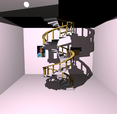
Figure 1-9: Texture-depth Extension Algorithm Results
When using this extension, set minification and magnification filter
to either GL_NEAREST or GL_LINEAR. Mipmap
minification filters of GL_NEAREST_MIPMAP_NEAREST,
GL_LINEAR_MIPMAP_NEAREST, GL_NEAREST_MIPMAP_LINEAR,
and GL_LINEAR_MIPMAP_LINEAR will give indeterminate results.
Table 1-8: Enumerated Types for Shadow and Depth-Texture
Extension
| Extended Area |
Enumerated Types |
Description |
|---|
| Texture Formats |
GL_DEPTH_COMPONENT,
GL_DEPTH_COMPONENT16_EXT,
GL_DEPTH_COMPONENT24_EXT,
GL_DEPTH_COMPONENT32_EXT
Default: N/A |
Texel formats which are useful when using shadow
texturing. |
| Texture Parameter |
GL_TEXTURE_COMPARE_EXT,
Default: GL_FALSE |
Enables comparison to the r coordinate when set to
true. |
| Texture Parameter |
GL_TEXTURE_DEPTH_EXT
Default: GL_FALSE |
Used to query if you have depth extension
available. |
| Texture Parameter |
GL_TEXTURE_COMPARE_OPERATOR_EXT,
GL_LEQUAL_R_EXT,
GL_GEQUAL_R_EXT
Default: GL_TEXTURE_LEQUAL_R_EXT |
Sets the particular type of comparison with the r
texture coordinate. |
- Set the GL_TEXTURE_COMPARE_EXT to GL_TRUE in
glTexParameter
- Set the GL_TEXTURE_COMPARE_OPERATOR_EXT to either
GL_TEXTURE_LEQUAL_R_EXT or GL_TEXTURE_GEQUAL_R_EXT using
glTexParameter.
- Use glTexImage with GL_DEPTH_COMPONENT to fill the
texture with the image which will be compared with the r
coordinate.
- Use glTexCoord3* to set the s, t, and
r texture coordinates at the vertices of the object to be
rendered.
This program renders a simple quadrilateral using the shadow texture extension
and the alpha test.
/* Put unusual includes */
#define TEXTURE_WIDTH 256
#define TEXTURE_HEIGHT 256
GLubyte texture[TEXTURE_WIDTH][TEXTURE_HEIGHT][1];
static void checkerPattern(int width,
int height,
int Checker_period)
{
int texelX, texelY;
int index ;
index = 0;
for (texelY = 0; texelY < height; texelY++) {
for (texelX = 0; texelX < width; texelX++) {
if (((texelX/Checker_period) % 2) ^
((texelY/Checker_period) % 2)) {
texture[texelX][texelY][0] = (GLubyte) 0; /* depth */
} else {
texture[texelX][texelY][0] = (GLubyte) 255; /* depth */
}
}
}
}
main code fragment
/* INSERT your favorite window create and map code here */
/* Set up transforms */
glMatrixMode(GL_PROJECTION);
glLoadIdentity ();
glOrtho (-10, 130., -10., 130., 1., -1.);
glMatrixMode(GL_MODELVIEW);
glLoadIdentity ();
glEnable(GL_DEPTH_TEST);
glEnable(GL_ALPHA_TEST);
glEnable(GL_TEXTURE_2D);
glDepthFunc(GL_LEQUAL);
glAlphaFunc(GL_GREATER, 0.5);
glClearDepth(1.0);
width = TEXTURE_WIDTH;
height = TEXTURE_HEIGHT;
checkerPattern( width,height, 64);
glTexParameterf(GL_TEXTURE_2D, GL_TEXTURE_WRAP_S,
GL_REPEAT);
glTexParameterf(GL_TEXTURE_2D, GL_TEXTURE_WRAP_T,
GL_REPEAT);
glTexParameterf(GL_TEXTURE_2D, GL_TEXTURE_MAG_FILTER,
GL_NEAREST);
glTexParameterf(GL_TEXTURE_2D, GL_TEXTURE_MIN_FILTER,
GL_NEAREST);
glTexParameterf(GL_TEXTURE_2D, GL_TEXTURE_COMPARE_EXT,
GL_TRUE);
glTexParameterf(GL_TEXTURE_2D, GL_TEXTURE_COMPARE_OPERATOR_EXT,
GL_TEXTURE_LEQUAL_R_EXT);
glTexEnvf(GL_TEXTURE_ENV, GL_TEXTURE_ENV_MODE, GL_REPLACE);
glTexImage2D(GL_TEXTURE_2D, 0, GL_DEPTH_COMPONENT16_EXT, width,
height, 0, GL_DEPTH_COMPONENT, GL_UNSIGNED_BYTE, &texture);
/* Render a red (background) and blue (primitive) checker pattern */
glClearColor(1.0, 0.0, 0.0, 1.0);
glClear(GL_COLOR_BUFFER_BIT|GL_DEPTH_BUFFER_BIT);
glColor3f(0.0, 0.0, 1.0);
glBegin(GL_QUADS);
glTexCoord3d(0.0, 0.0, 0.0);
glVertex3f(0.5, 0.5, 0.);
glTexCoord3d(0.0, 1.0, 1.0);
glVertex3f(0.5, 106.5, 0.);
glTexCoord3d(1.0, 1.0, 1.0);
glVertex3f(106.5, 106.5, 0.);
glTexCoord3d(1.0, 0.0, 0.0);
glVertex3f(106.5, 0.5, 0.);
glEnd();
Figure 1-10 shows the results from executing the program.
Figure 1-10: Results from Shadow Texturing
For related information, see the function glTexParameter.
The texture lighting extension defines a mechanism for applications to request
that color originating from specular lighting be added to the fragment color
after texture application. This is referred to as preLight texturing.
Table 1-9: Enumerated Types for preLight Texturing
| Extended area |
Enumerated Types |
Description |
|---|
| Texture Environment |
GL_TEXTURE_LIGHTING_MODE_HP,
GL_TEXTURE_PRE_SPECULAR_HP,
GL_TEXTURE_POST_SPECULAR_HP
Default: N/A |
pname and param parameters for
glTexEnv. |
You need to add the following preLight texturing code fragments to
the normal texturing program that also has lighting.
glTexEnv[if](GL_TEXTURE_ENV, GL_TEXTURE_LIGHTING_MODE_HP,
GL_TEXTURE_PRE_SPECULAR_HP);
or
GLfloat appMode=GL_TEXTURE_PRE_SPECULAR_HP; glTexEnvf(GL_TEXTURE_ENV,
GL_TEXTURE_LIGHTING_MODE_HP, &appMode);
The results from using preLight texturing are given in Figure 1-11.
Note that the top image is without prelight texturing, and the bottom is with
preLight texturing. The left half of both images is the untextured
specular-lighted image, and the right half of both images uses
GL_REPLACE texturing.
Figure 1-11: Results from Prelight Texturing
For related information, see the function glTexEnv.
This occlusion culling extension defines a mechanism whereby an application
can determine the non-visibility of some set of geometry based on whether an
encompassing set of geometry is non-visible. In general, this feature does not
guarantee that the target geometry is visible when the test fails, but is
accurate with regard to non-visibility.
Typical usage of this feature would include testing the bounding boxes of
complex objects for visibility. If the bounding box is not visible, then it
is known that the object is not visible and need not be rendered.
The following is a sample code segment that shows a simple usage of occlusion
culling.
/* Turn off writes to depth and color buffers */
glDepthMask(GL_FALSE);
glColorMask (GL_FALSE, GL_FALSE, GL_FALSE);
/* Enable Occlusion Culling test */
glEnable(GL_OCCLUSION_TEST_HP);
for (i=0; i < numParts; i++) {
/* Render your favorite bounding box */
renderBoundingBox(i);
/* If bounding box is visible, render part */
glGetBooleanv(GL_OCCLUSION_RESULT_HP, &result);
if (result) {
glColorMask(GL_TRUE, GL_TRUE, GL_TRUE);
glDepthMask(GL_TRUE);
renderPart(i);
glDepthMask(GL_FALSE);
glColorMask (GL_FALSE, GL_FALSE, GL_FALSE);
}
}
/* Disable Occlusion Culling test */
glDisable(GL_OCCLUSION_TEST_HP);
/* Turn on writes to depth and color buffers */
glColorMask(GL_TRUE, GL_TRUE, GL_TRUE);
glDepthMask(GL_TRUE);
The key idea behind occlusion culling is that the bounding box is much simpler
(i.e., fewer vertices) than the part itself. Occlusion culling provides a
quick means to test non-visibility of a part by testing its bounding box.
It should also be noted that this occlusion culling functionality is very
useful for viewing frustum culling. If a part's bounding box is not visible
for any reason (not just because it's occluded in the Z-buffer) this
test will give correct results.
To maximize the probability that an object is occluded by other objects in a
scene, the database should be sorted and rendered from front to back. Also,
the database may be sorted hierarchically such that the outer objects are
rendered first and the inner are rendered last. An example would be rendering
the body of an automobile first and the engine and transmission last. In this
way, the engine would not be rendered due to the bounding box test indicating
that the engine is not visible.
Table 1-10: Enumerated Types for Occlusion
| Extended Area |
Enumerated Types |
Description |
|---|
| Enable/Disable/IsEnabled |
GL_OCCLUSION_TEST_HP
Default: Disabled |
pname variable |
| Get* |
GL_OCCLUSION_TEST_RESULT_HP
Default: Zero (0) |
pname variable |
For related information, see the functions: glGet, glEnable, glDisable, and glIsEnabled.
The autogen MIP-map extension introduces a side effect to the modification of
the base level texture map. When enabled, any change to the base-level
texture map will cause the computation of a complete MIP map for that base
level. The internal formats and border widths of the derived MIP map will
match those of the base map, and the dimensions of the derived MIP map follow
the requirements set forth in OpenGL for a valid MIP map. A simple 22 box filter is used to generate the MIP-map
levels.
Table 1-11: Enumerated Types for Occlusion
| Extended Area |
Enumerated Types |
Description |
|---|
| Texture Parameter |
GL_GENERATE_MIPMAP_EXT
Default: GL_FALSE |
Enables autogen MIP map. |
To use the autogen MIP-map extension, set GL_GENERATE_MIPMAP_EXT to
GL_TRUE in glTexParameter. For example, here is a code
fragment that uses this extension:
glTexParameter[if](GL_TEXTURE_2D, GL_GENERATE_MIPMAP_EXT, GL_TRUE);
For related information on this extension, see the function: glTexParameter.
HP's implementation of OpenGL includes two GLX extensions that deal with
extended GLX visual information that is not included in the OpenGL 1.1
Standard. These extensions are both supported by HP's implementation of the
OpenGL API library, but prior to using them,
glXQueryExtensionsString should be called to verify that the
extensions are supported on the target display.
The GLX_EXT_visual_info extension provides additional GLX visual
information and enhanced control of GLX Visual selection. The enumerated
types listed below can be passed to either glXChooseVisual, or glXGetConfig to specify or
inquire the visual type or transparency capabilities.
Table 1-12: Enumerated Types for GLX Visual
Information
| Extended Area |
Enumerated Types |
Description |
|---|
| Visual Type |
GLX_TRUE_COLOR_EXT,
GLX_DIRECT_COLOR_EXT,
GLX_PSEUDO_COLOR_EXT,
GLX_STATIC_COLOR_EXT (1),
GLX_GRAY_SCALE_EXT (1),
GLX_STATIC_GRAY_EXT (1)
Default: N/A |
Values associated with the GLX_X_VISUAL_TYPE_EXT enumerated
type. |
Visual Transparency
Capabilities |
GLX_NONE_EXT,
GLX_TRANSPARENT_RGB_EXT (1),
GLX_TRANSPARENT_INDEX_EXT
Default: GLX_NONE_EXT |
Values associated with the GLX_TRANSPARENT_TYPE_EXT
enumerated type. |
- These enumerated types are supported through the GLX client-side
API library, but there are currently no HP X Server GLX visuals
with these capabilities. They can still be used to query any
Server and will operate properly if connected to a non-HP server
with GLX support for these visual capabilities.
|
The enumerated types listed below can be used only through glXGetConfig when it is
known that the GLX visual being queried supports transparency or in other
words, has a GLX_TRANSPARENT_TYPE_EXT property other than
GLX_NONE_EXT.
Table 1-13: Enumerated Types for GLX Visual
Transparency
| Extended Area |
Enumerated Types |
Description |
|---|
Transparency
Index for
PseudoColor
Visuals |
GLX_TRANSPARENT_INDEX_VALUE_EXT
Default: N/A |
Returns the Pixel Index for the transparent color in a
GLX_TRANSPARENT_INDEX_EXT visual. |
Transparency
Values for
RGBA
Visuals |
GLX_TRANSPARENT_RED_VALUE_EXT,
GLX_TRANSPARENT_GREEN_VALUE_EXT,
GLX_TRANSPARENT_BLUE_VALUE_EXT,
GLX_TRANSPARENT_ALPHA_VALUE_EXT
Default: N/A |
Returns the RGBA data values for the transparent color in a
GLX_TRANSPARENT_RGB_EXT GLX visual (not supported on HP
servers). |
Note that both of the following segments assume that the
GLX_EXT_visual_info extension exists for dpy, which is a
pre-existing display connection to an X Server.
Here is a sample code segment that forces selection only of a TrueColor
visual.
Display *dpy;
XVisualInfo *vInfo;
int attrList[] = {GL_USE_GL,
GLX_X_VISUAL_TYPE_EXT,
GLX_TRUE_COLOR_EXT,
None};
vinfo = glXChooseVisual(dpy, XDefaultScreen(dpy), &attrList);
The following sample is a code segment that selects an overlay visual with
index transparency, and then obtains the Pixel index for the transparent
color.
Display *dpy;
XVisualInfo *visInfo;
int transparentPixel;
int attrList[] = {GL_USE_GL,
GLX_LEVEL, 1,
GLX_TRANSPARENT_TYPE_EXT,
GLX_TRANSPARENT_INDEX_EXT,
None};
visInfo = glXChooseVisual(dpy, XDefaultScreen(dpy), &attrList);
if (visInfo != NULL) {
glXGetConfig(dpy, visInfo, GLX_TRANSPARENT_INDEX_VALUE_EXT,
&transparentPixel);
}
The GLX_EXT_visual_rating extension provides additional GLX visual
information which applies rating properties to GLX visuals. The enumerated
types listed below can be passed to either glXChooseVisual, or glXGetConfig to specify or
inquire visual rating information.
Table 1-14: Enumerated Types for GLX Visual Rating
| Extended Area |
Enumerated Types |
Description |
|---|
| Visual Rating |
GLX_NONE_EXT,
GLX_SLOW_VISUAL_EXT,
GLX_NON_CONFORMANT_VISUAL_EXT
Default: N/A |
Values associated with the GLX_VISUAL_CAVEAT_EXT enumerated
type. |
Note that all current HP GLX visuals are rated as GLX_NONE_EXT. This
extension is implemented for possible future visual support and for use with
non-HP servers. Coding to use the GLX_EXT_visual_rating extension is
similar to the segments listed above for the GLX_EXT_visual_info
extension.
This section provides the details for several of HP's rendering capabilities.
These rendering capabilities range from the way HP implements its default
visuals to the way HP deals with the decomposition of concave quadrilaterals.
Instead of placing the default visual in the deepest image buffer, HP puts the
default visual in the overlay planes.
The Virtual Memory Driver's implementation of fog applies fog per
fragment. Hardware devices implement EXP and EXP2 fog per fragment and linear fog per
vertex.
A quadrilateral has four vertices that are coplanar. When this quadrilateral
is twisted and you look at a front view of it on the display, there appears to
be a fifth vertex. This fifth vertex which is not a true vertex will have no
attributes, therefore, the color at what appears to be the intersection of two
lines will in most cases be different from what is expected. HP treats the
two parts of the bow tie as two separate triangles that have attributes
assigned to their vertices. This special rendering process takes care of the
color problem at the non-existent fifth vertex.
To learn how other implementations of OpenGL deal with bow-tie quadrilaterals,
read the section "Describing Points, Lines, and Polygons" in Chapter 2 of the
OpenGL Programming Guide.
HP determines whether the concave quadrilateral will become front-facing or
back-facing prior to dividing the quadrilateral into triangles. HP then
divides the surface into two triangles between vertices zero and two or one
and three depending on the vertex causing concavity.
HP's implementation of this specification is indeterminate as defined by the
OpenGL standard.
If dithering is enabled in indexed visuals, 2D functions such as
glDrawPixels() and glBitmap() will not be dithered.
![[Up]](../buttons/ArrowUp.gif) Environment Variables
Here is a list of environment variables used by HP's implementation of OpenGL.
Environment Variables
Here is a list of environment variables used by HP's implementation of OpenGL.
- HPOGL_ALLOW_LOCAL_INDIRECT_CONTEXTS
- This variable may be set if a need arises to really create a local
indirect context. By default, if an indirect context is requested for a
local HP display connection, a direct context will be created instead
because the performance will be much better.
- HPOGL_ENABLE_MIT_SHMEM
- When rendering locally using the VM Driver, this variable allows the
server and client to look at the rendering buffer at the same time. This
variable has no effect through DHA. It merely eliminates the data
transfer for XPutImage() that is done by VMD. This only offers a
performance improvement on simple wireframes. Under most circumstances,
it does not provide any performance improvements.
- HPOGL_FORCE_VGL
- This variable can be set to force HP's Virtual GL (VGL) rendering mode
using VMD. This differs from HPOGL_FORCE_VMD in that the GLX Visual list
and other GLX extension information is not retrieved from the GLX
Server extension, but is rather synthesized from standard X Visual
information and the capabilities known to exist in VMD.
- HPOGL_FORCE_VMD
- This variable forces clients to render through the VMD. This variable
can be used as a temporary fix and/or a diagnostic. You should set this
variable when a rendering defect in the hardware device driver is
suspected. When this variable is set, rendering speed will slow down. If
rendering is identical in both hardware and software, then this may
indicate a problem in the application code.
- HPOGL_LIB_PATH
- This variable can be used to load OpenGL driver libraries from a
directory outside the standard LIB_PATH. This variable should be
set to the actual directory the libraries are in, with or without a
trailing '/'.
- HPOGL_LIGHTING_SPACE
- This variable allows the user to specify the coordinate space to be
used for lighting. By default, HP's implementation of the OpenGL will
select the lighting space. Possible values are:
HPOGL_LIGHTING_SPACE=OC
HPOGL_LIGHTING_SPACE=EC
where OC equals Object Coordinates and EC equals Eye
Coordinates. For details on the lighting space, see the sections "Lighting Space" and "Optimization of
Lighting" found in Chapter 5.
- HPOGL_TXTR_SHMEM_THRESHOLD
- This variable sets a fence for the use of process memory vs. shared
memory. Any 2D or 3D texture that has a size greater than or equal to the
threshold set is stored in shared memory. The initial value is set to
10241024 bytes. This variable
should be set to the byte size desired for shared memory usage.
The performance of HP OpenGL double buffering has been improved for Release
1.05 of HP's implementation of OpenGL 1.1. With this performance enhancement,
there is a low probability that minor image tearing may be visible during
buffer-swap operations. The majority of OpenGL applications will see no
difference in the visual quality of double buffering. However, this tearing
may be noticed by some OpenGL applications that render simultaneously to
multiple windows.
Two environment variables can be set in an application environment to
control whether or not the new faster buffer swapping method is in effect:
- HPOGL_DSM_ENABLE_FAST_BUFFER_SWAP
- When set to any non-NULL value, the new or faster double
buffering method will be used. (This is the default behavior and does not
need to be set except to override glHint as discussed below)
- HPOGL_DSM_DISABLE_FAST_BUFFER_SWAP
- When set to any non-NULL value, the old or slower double
buffering method will be used.
Additionally, an application can programmatically switch between the slower
and faster double buffering methods using the following new glHint calls:
- glHint(GL_BUFFER_SWAP_MODE_HINT_HP, GL_FASTEST);
- Switches to the faster double buffering method.
- glHint(GL_BUFFER_SWAP_MODE_HINT_HP, GL_NICEST);
- Switches to the slower double buffering method.
Note that setting either HPOGL_DSM_ENABLE_FAST_BUFFER_SWAP or
HPOGL_DSM_DISABLE_FAST_BUFFER_SWAP in the application environment
will disable and thus override the behavior of the new glHint calls.